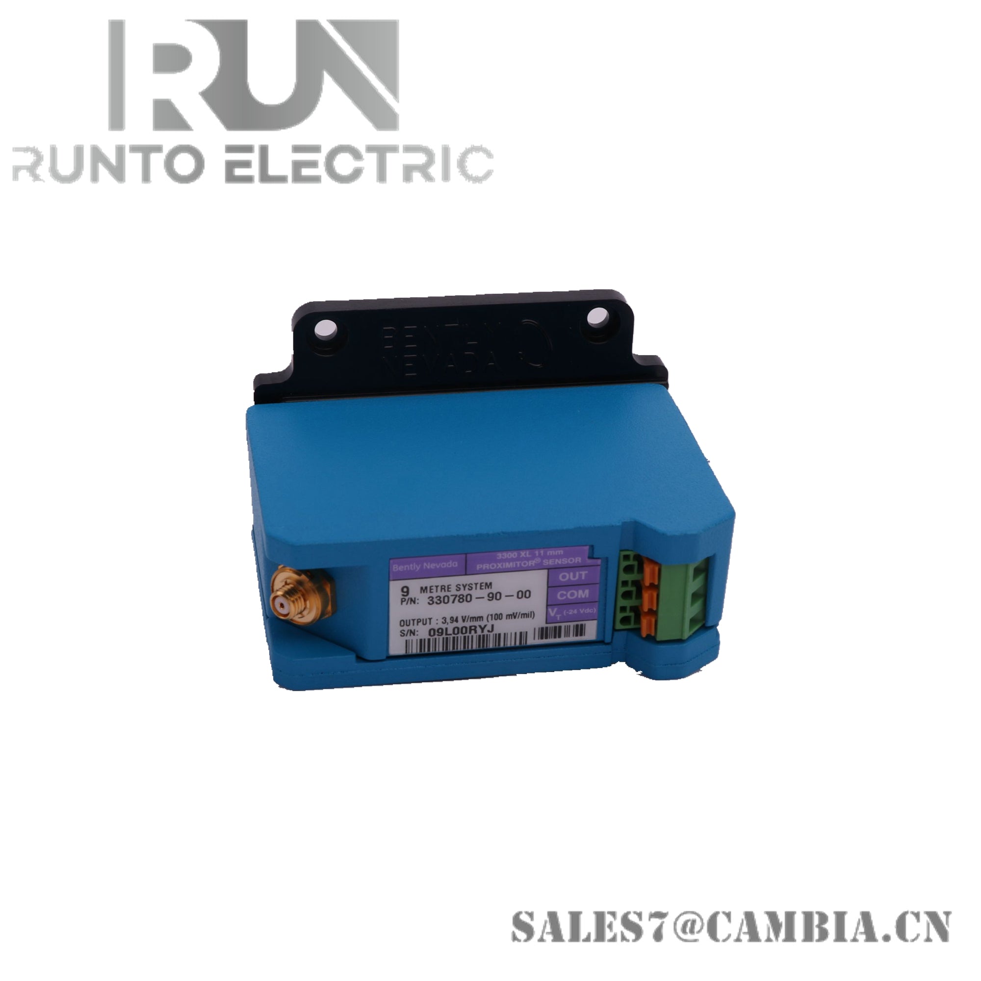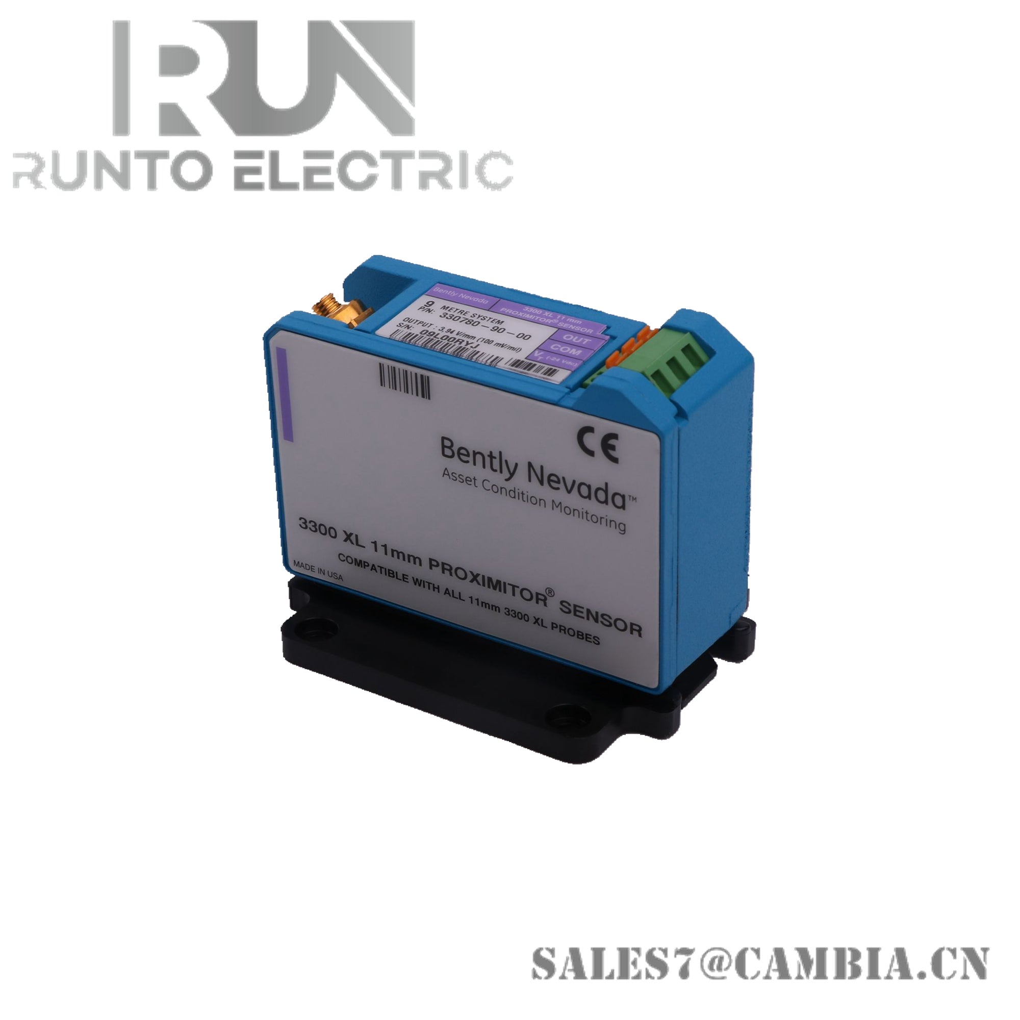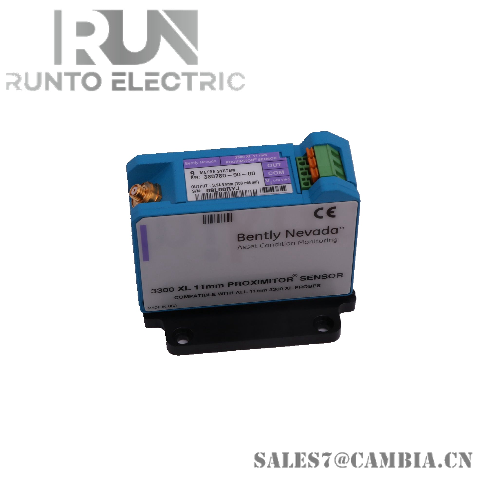
Bently Nevada 330780-50-05 Proximitor Sensor

Bently Nevada 330780-50-05 3300 XL 11 mm Proximitor Sensor
The Bently Nevada 330780-50-05, also cataloged as the 330780 Proximitor Sensor, operates as a dedicated hardware component for proximity signal conditioning within the 3300 XL monitoring system.
Suffix Breakdown & Model Matrix
- 50: Cable length option, 5.0 metres (16.4 feet) system length
- 05: Connector and agency approval option, multiple certifications
Hardware Specifications
| Parameter | Specification |
|---|---|
| Model | 330780-50-05 |
| Brand | Bently Nevada |
| Origin | U.S.A |
| Weight | Standard sensor mass (shipping weight varies) |
| Dimensions | DIN mount form factor |
| Operating Temp | -52 deg C to +100 deg C |
| Storage Temp | -61 deg C to +212 deg F |
| Power Consumption | 12 mA maximum |
| Function | Signal conditioning for 11 mm proximity probes |
| Compatibility | Works with 3300 XL 11 mm probes and extension cables |
| Power Requirement | Standard -24 VDC transducer supply |
Rotor Dynamics Monitoring
The sensor integrates eddy-current probe scaling to ensure accurate displacement measurement. Gap voltage validation at -10 VDC reference points maintains linearity across the operating range. Cross-talk suppression is achieved through coaxial shielding, enabling precise rotor dynamics monitoring in multi-channel configurations.
Frequently Asked Questions
Q: Can the 330780-50-05 be operated with non-standard power supplies? A: No, it requires a standard -24 VDC transducer supply; deviation may reduce measurement accuracy.
Q: What is the recommended installation environment? A: The sensor is designed for industrial machinery monitoring; ensure ambient temperature remains within -52 deg C to +100 deg C.
Q: Does the sensor support redundant channel switching? A: Redundancy is managed at the system level; the sensor itself does not provide internal failover switching.
Field Installation Guidelines
- Mount securely on DIN rail with proper mechanical engagement.
- Maintain shield grounding at a single termination point to avoid ground loops.
- Route extension cables separately from high-voltage conductors to minimize induced interference.
- Verify probe gap voltage alignment (-10 VDC reference) during commissioning.
Bently Nevada 330780-50-05 Proximitor Sensor