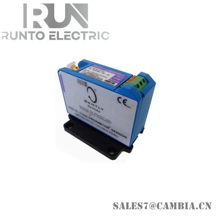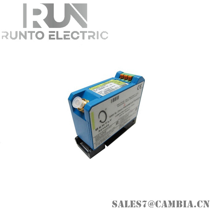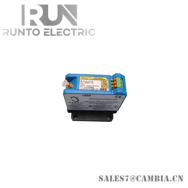
Bently Nevada 24583-04 High Temp Proximitor Switch

Bently Nevada 24583-04 High Temp Proximitor Switch
The Bently Nevada 24583-04, also cataloged as the 24583 High Temp Proximitor Switch, operates as a dedicated hardware component for non-contact shaft displacement and vibration signal conversion within Bently Nevada proximity transducer systems. The device interfaces with a high-temperature probe assembly, converting eddy-current measurement data into an analog voltage signal proportional to target movement. It supports operation in elevated thermal environments while maintaining a defined transducer scale factor.
Hardware Specifications
| Parameter | Specification |
|---|---|
| Model | 24583-04 |
| Brand | Bently Nevada |
| Origin | United States |
| Product Type | High Temp Proximitor Switch |
| Probe Diameter | 50 mm (2.00 in.) |
| Operating Temp | Up to 538 deg C (1000 deg F) |
| Power Supply | -18 VDC to -24 VDC |
| Scale Factor | 10 mV/mil (0.4 V/mm) |
| Output Signal | Analog voltage proportional to displacement or vibration |
| Mounting | Chassis mountable |
| Weight | Approximately 0.29 kg |
| Power Consumption | Not specified in available data |
Eddy-Current Probe Scaling and Gap Validation
The 24583-04 functions as part of an eddy-current proximity measurement chain in which the probe, extension cable, and Proximitor assembly are calibrated as a matched system. The specified scale factor of 10 mV/mil establishes the relationship between target movement and output signal variation.
For installation and commissioning, transducer systems typically require verification of probe gap voltage to confirm proper target positioning and measurement linearity. In rotating machinery applications, gap validation assists in maintaining displacement measurement consistency and supports rotor dynamic analysis functions performed by associated monitoring systems.
Frequently Asked Questions
Q: Can the 24583-04 be used as a stand-alone displacement sensor?
A: No. The device is intended to operate as part of a complete proximity transducer system consisting of a compatible high-temperature probe, associated cabling, and signal conditioning electronics.
Q: Does the module provide a digital communication interface?
A: No. Available specifications indicate an analog voltage output proportional to measured displacement or vibration.
Q: What is the primary purpose of scale factor verification during commissioning?
A: Scale factor verification confirms that displacement-related voltage output corresponds to the calibrated transducer response and that the sensing chain is operating within its intended measurement range.
Field Installation Guidelines
-
Mount the unit on a mechanically stable chassis or equipment base to minimize vibration-induced wiring stress.
-
Route probe cables separately from high-voltage, motor, and variable-frequency drive conductors to reduce electromagnetic interference.
-
Maintain shielding continuity according to plant grounding standards and terminate shields at the designated instrumentation ground point.
-
Verify probe-to-target gap conditions before placing machinery into service.
-
Avoid excessive cable bending, crushing, or unsupported cable runs that may alter transducer performance.
-
Confirm supply voltage remains within the specified -18 VDC to -24 VDC range before energizing the sensing circuit.
-
After installation, validate analog output response against known shaft position or displacement conditions where practical.
Frequently Referenced Applications
-
Shaft displacement monitoring
-
High-temperature machinery position sensing
-
Rotor vibration measurement systems
-
Turbomachinery protection instrumentation
-
TSI monitoring architectures
Bently Nevada 24583-04 High Temp Proximitor Switch