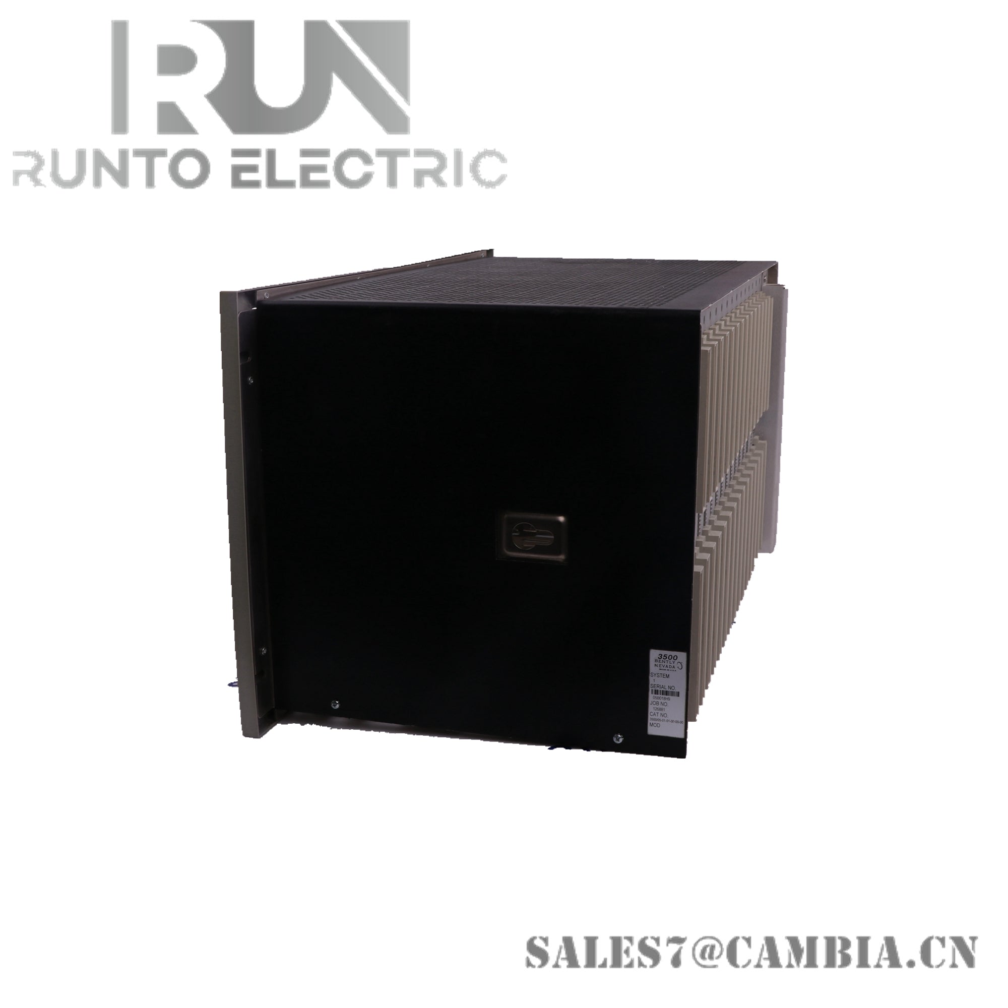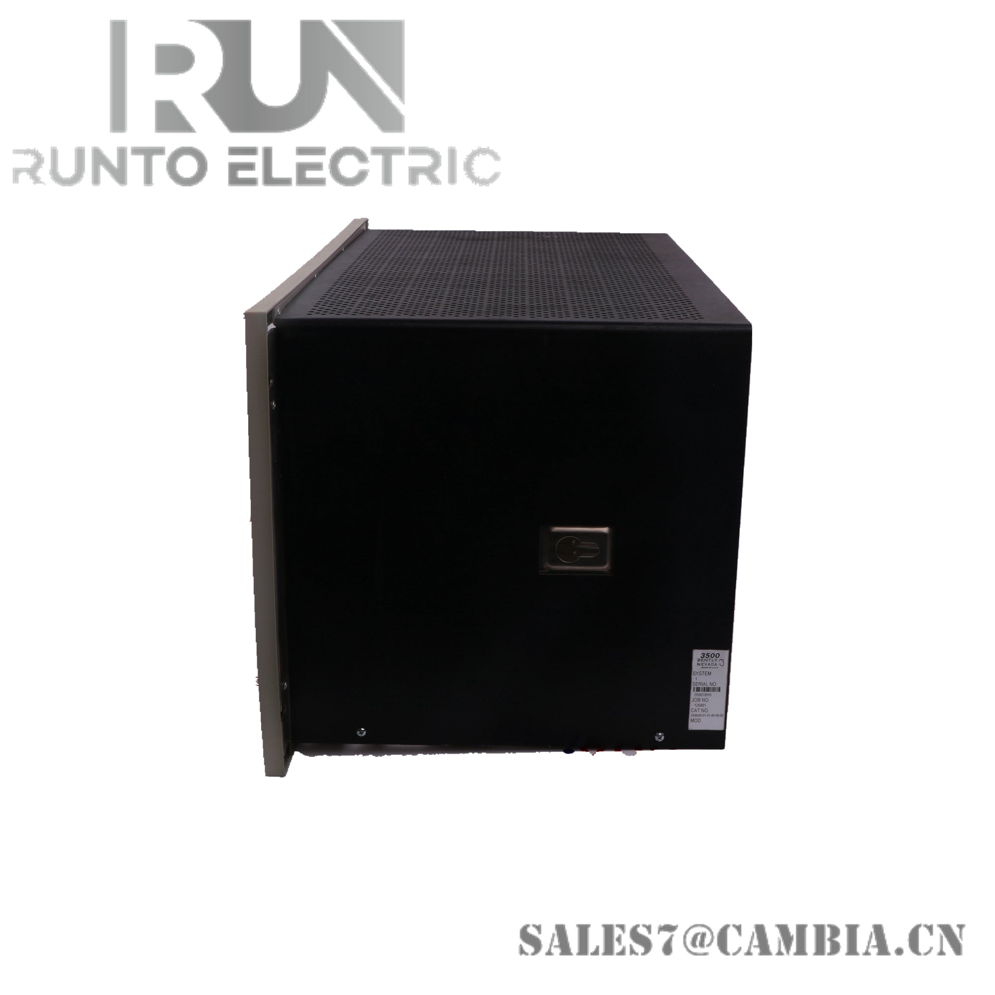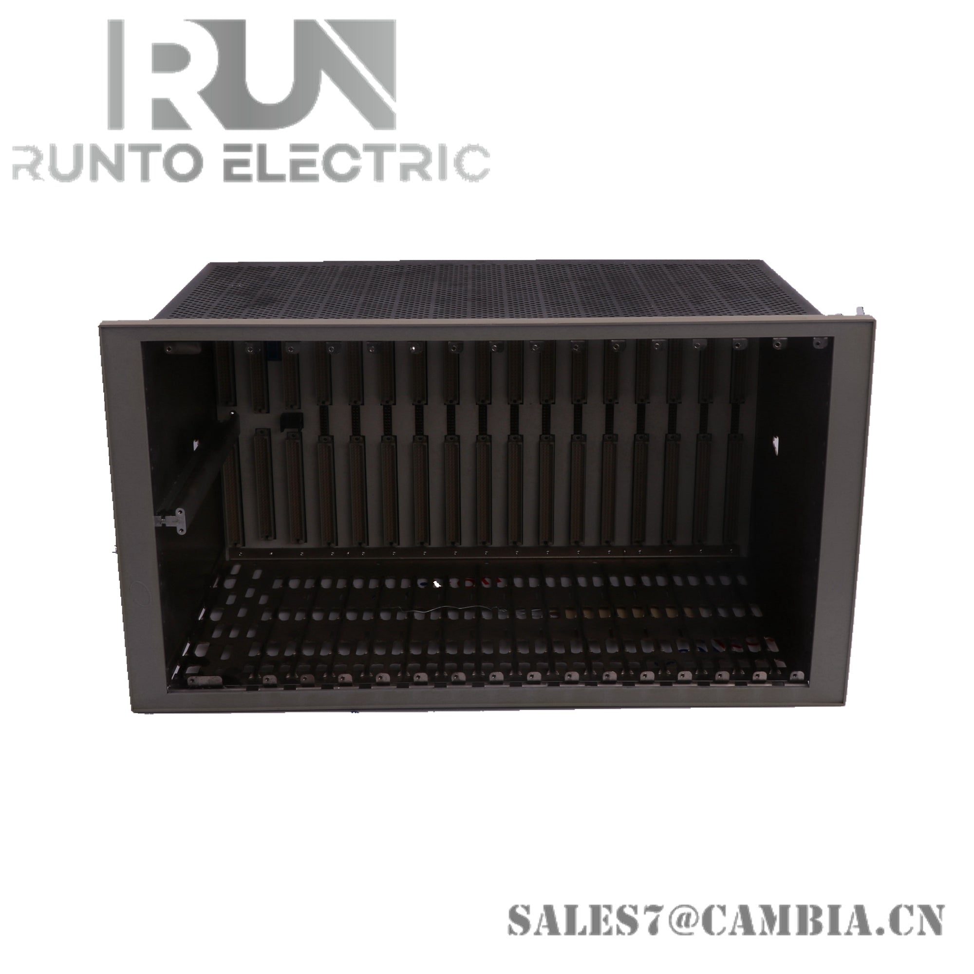
Bently Nevada 3300/05-24-00-00 10 Slot Rack

Bently Nevada 3300/05-24-00-00 10 Slot Rack
The Bently Nevada 3300/05-24-00-00, also cataloged as the 3300/05 Rack, operates as a dedicated hardware enclosure for housing power, system monitor, and machinery protection modules within the 3300 Monitoring System.
Suffix Breakdown & Model Matrix
- 3300/05: Core Bently Nevada 3300 Monitoring System Mainframe Rack
- 24: 10-slot configuration (positions for 10 modules)
- 00: Standard panel mount installation option
- 00: No agency approvals (factory standard configuration)
Hardware Specifications
| Parameter | Specification |
|---|---|
| Model | 3300/05-24-00-00 |
| Brand | Bently Nevada |
| Origin | U.S.A |
| Weight | Not specified (rack-only enclosure) |
| Dimensions | Standard 19-inch rack-mount configuration |
| Operating Temp | -20 deg C to +60 deg C (-4 F to 140 F) |
| Storage Temp | -40 deg C to +85 deg C (-40 F to 185 F) |
| Power Consumption | Defined by installed modules (rack provides backplane distribution only) |
| Slot Capacity | 10 slots (1 Power Supply, 1 System Monitor, 8 Monitoring Modules) |
| Material | Injection-molded conductive anti-static plastic |
| Wiring | Backplane modular design, no manual internal wiring |
| Humidity | 95% non-condensing |
Rotor Dynamics and Cross-Talk Suppression
The 3300 rack architecture supports proximitor and vibration monitoring modules where rotor dynamics analysis is essential. Backplane design incorporates signal routing that minimizes cross-talk between adjacent channels, ensuring accurate displacement and velocity measurements. Gap voltage validation (-10 VDC targets) is maintained across probe channels, providing deterministic alarm thresholds for machinery protection.
Frequently Asked Questions (FAQ)
Q: Can the rack slots be reallocated for different module types? A: Positions 1 and 2 are fixed for Power Supply and System Monitor modules; positions 3–10 are flexible for protection monitors.
Q: Does the rack provide its own power regulation? A: No. Power regulation is handled by the installed Power Supply Module; the rack only distributes via the backplane.
Q: How are rear panel connections aligned? A: Each rear panel position corresponds directly to the front slot, enabling signal input and relay module integration.
Field Installation Guidelines
- Mount the rack in a standard 19-inch panel using factory panel-mount brackets.
- Ensure conductive grounding of the rack chassis to dissipate electrostatic discharge.
- Maintain separation between signal cabling and high-voltage wiring to reduce interference.
- Verify slot allocation before installation: Power Supply in position 1, System Monitor in position 2.
- Confirm environmental conditions meet specified operating and storage ranges.
- Secure rear panel connections to match front slot assignments for signal integrity.
Bently Nevada 3300/05-24-00-00 10 Slot Rack