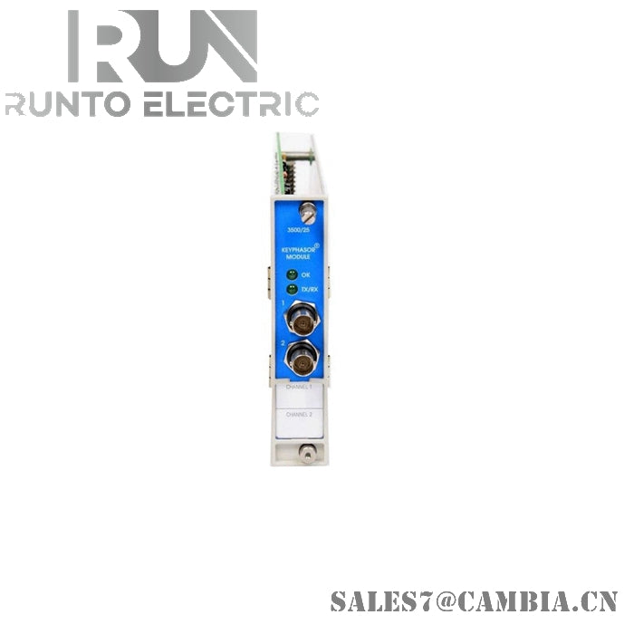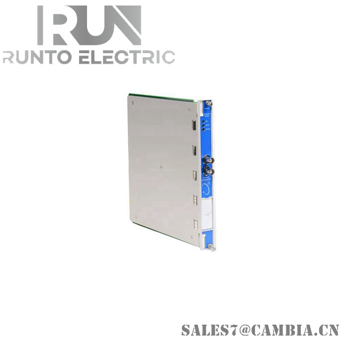
Bently Nevada 3300/20-13-02-01-00-00 Dual Thrust Monitor

Bently Nevada 3300/20-13-02-01-00-00 Dual Thrust Monitor
The Bently Nevada 3300/20-13-02-01-00-00, also cataloged as the 3300/20 Dual Thrust Monitor, operates as a dual-channel thrust position measurement module within the 3300 machinery protection system.
Suffix Breakdown & Model Matrix
- 3300/20: Dual Thrust Position Monitor
- 13: Scale range option — 40-0-40 mils (compatible with 7200 5 mm/8 mm or 3300 8 mm Proximitor sensors)
- 02: CSA/NRTL/C approval (Class 1, Division 2, Groups A, B, C, D)
- 01: Internal barrier option installed on both channels
- 00: Standard English display panels
- 00: No trip multiply functionality
Hardware Specifications
| Parameter | Specification |
|---|---|
| Model | 3300/20-13-02-01-00-00 |
| Brand | Bently Nevada |
| Origin | U.S.A |
| Weight | ~1.0 kg |
| Dimensions | Rack slot module (dual-channel width) |
| Operating Temp | 0 deg C to +65 deg C (+32 F to +149 F) |
| Storage Temp | -40 deg C to +85 deg C (-40 F to +185 F) |
| Relative Humidity | Up to 95%, non-condensing |
| Power Consumption | 7.7 W nominal |
| Inputs | Two independent proximity transducer channels |
| Signal Input | -1 VDC to -26 VDC (nominal 0 to -10 VDC scale range) |
| Input Impedance | 10 kΩ nominal |
| Alarms | Alert and Danger setpoints configurable from 0% to 100% of full scale |
| Relays | Epoxy-sealed SPDT relays per channel |
| Recorder Outputs | +4 to +20 mA or 0 to -10 VDC (user-selectable per channel) |
Eddy-Current Probe Scaling and Gap Voltage Validation
The 3300/20 thrust monitor applies linear scale factors aligned with eddy-current proximity probes, ensuring accurate conversion of shaft displacement signals. Gap voltage validation against -10 VDC reference targets confirms probe installation integrity. This mechanism supports rotor dynamics analysis and suppresses cross-talk between dual channels, maintaining deterministic alarm execution.
Frequently Asked Questions (FAQ)
Q: Can the 3300/20-13-02-01-00-00 module be hot-swapped? A: No. Rack power must be removed before insertion or removal to avoid backplane disruption.
Q: How are alarm thresholds configured? A: Alert and Danger setpoints are configured via rack interface, adjustable from 0% to 100% of full scale.
Q: What recorder outputs are available? A: Each channel provides user-selectable +4 to +20 mA or 0 to -10 VDC outputs.
Field Installation Guidelines
- Install the module in designated rack slots with full connector engagement.
- Ensure proximity probe cabling is shielded and grounded at the rack end to minimize induced noise.
- Maintain probe gap voltage near -10 VDC during installation for valid displacement scaling.
- Route dual-channel inputs separately to reduce cross-talk.
- Configure alert and danger setpoints before commissioning.
- Verify environmental conditions meet specified operating and storage ranges.
Bently Nevada 3300/20-13-02-01-00-00 Dual Thrust Monitor