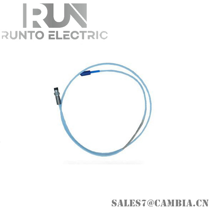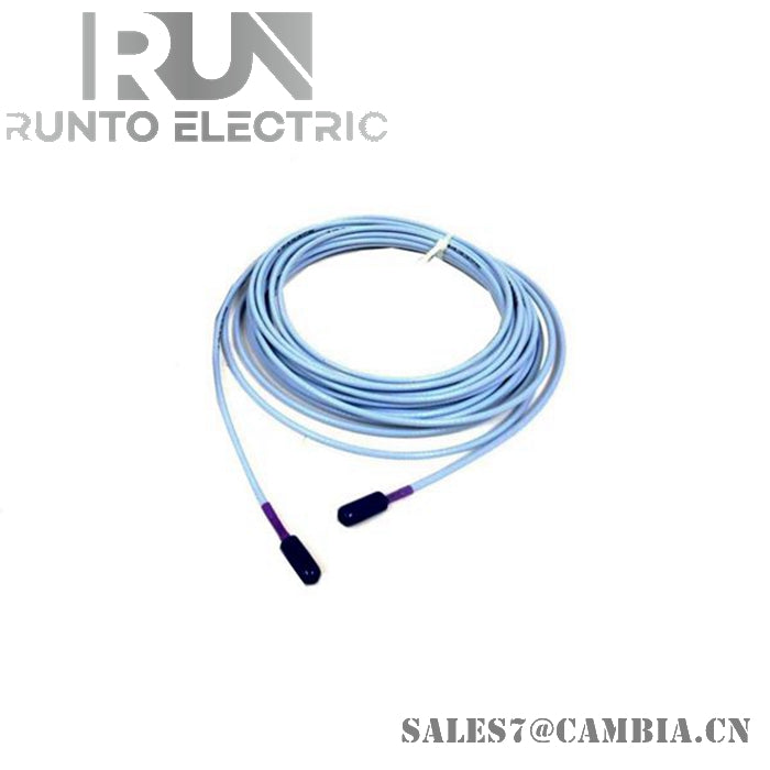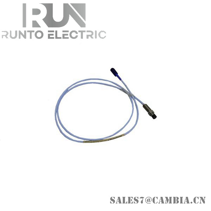
Bently Nevada 330104-00-04-10-02-05 3300 XL 8 mm Proximity Probe

Bently Nevada 330104-00-04-10-02-05 3300 XL 8 mm Proximity Probe
The Bently Nevada 330104-00-04-10-02-05, also cataloged as the 3300 XL 8 mm Proximity Probe, operates as a dedicated hardware component for non-contact shaft vibration and position monitoring within machinery protection systems. The integrated eddy-current sensor coil emits a high-frequency electromagnetic field at the probe tip to measure real-time dynamic gap variations against a conductive target shaft.
Suffix Breakdown & Model Matrix
-
Unthreaded Length Option (-00): 0 mm unthreaded length (M10 x 1 threaded case with armor).
-
Overall Case Length Option (-04): 40 mm overall case length.
-
Total Length Option (-10): 1.0 meter (3.3 feet) total length.
-
Connector and Cable-Type Option (-02): Miniature coaxial ClickLoc connector with armored standard cable.
-
Agency Approval Option (-05): Multiple hazardous area approvals (CSA, ATEX, IECEx).
Hardware Specifications
| Parameter | Specification |
| Model | 330104-00-04-10-02-05 |
| Brand | Bently Nevada |
| Origin | USA |
| Weight | 2.0 kg |
| Dimensions | Case: 40 mm (M10 x 1); Cable Length: 1.0 m (3.3 ft) |
| Operating Temp | -51 deg C to +177 deg C |
| Power Consumption | Powered via 3300 XL Proximitor Sensor loop (-24 VDC system connection) |
| Probe Tip Material | Polyphenylene sulfide (PPS) |
| Probe Case Material | AISI 303 or 304 stainless steel (SST) |
| Pressure Seal | Viton O-ring between probe tip and case |
| Connector Type | Miniature coaxial ClickLoc connector |
Mechanical Monitoring & Eddy-Current Probe Scaling
The probe system provides a standardized scale factor of 7.87 V/mm (200 mV/mil) when properly mated with a matching 3300 XL Proximitor Sensor and extension cable assembly. During physical mounting, gap voltage validation requires setting the static center point of the linear operating region to -10 VDC relative to the observed rotor target surface. Proper structural installation minimizes cross-talk suppression issues when adjacent probes are mounted in 90-deg orthogonal configurations, preserving signal fidelity across complex rotor dynamics profiles.
Frequently Asked Questions
Q: What mounting procedure ensures proper physical baseline alignment for this probe?
A: Mechanically adjust the probe position within the M10 x 1 threaded mount while measuring the Proximitor Sensor DC output voltage. Adjust until the output reaches -10 VDC, which corresponds to the midpoint of the calibrated linear range.
Q: How does the armored cable option affect field physical installation?
A: The stainless steel armor provides physical damage resistance in severe industrial environments. However, ensure that the bend radius remains within specified limits to prevent internal coaxial cable crimping and dielectric degradation.
Field Installation Guidelines
-
Maintain recommended probe-to-probe physical clearance to prevent cross-talk and mutual inductive coupling between adjacent sensor channels.
-
Verify that the target material matches standard factory calibration assumptions (AISI 4140 steel) unless specific scale factor compensation is configured in the monitor.
-
Lock the coaxial ClickLoc connector securely and insulate the terminal connection with protective boots or self-fusing silicone tape when installed in moist locations.
-
Ground the probe case securely through the mechanical mounting block while keeping the coaxial cable shield isolated from intermediate conduit junctions.
Bently Nevada 330104-00-04-10-02-05 3300 XL 8 mm Proximity Probe