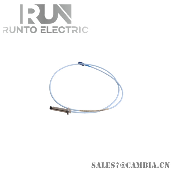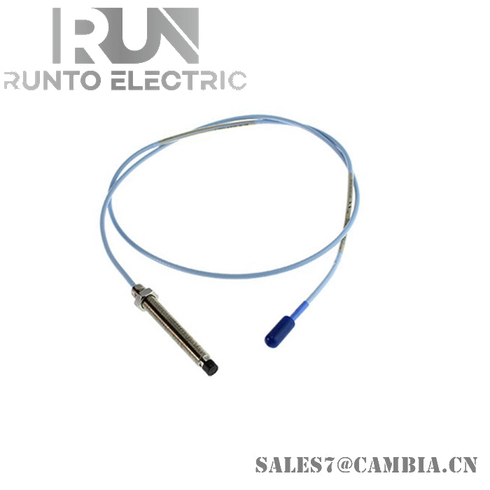
Bently Nevada 330104-00-05-10-02-00 3300 XL 8 mm Proximity Probe

Bently Nevada 330104-00-05-10-02-00 3300 XL 8 mm Proximity Probe
The Bently Nevada 330104-00-05-10-02-00 serves as the primary 3300 XL 8 mm Proximity Probe utilized to execute non-contact shaft vibration and displacement measurements across machinery protection system platforms. The high-frequency eddy-current coil embedded in the probe tip measures dynamic physical gap changes relative to a conductive rotating target shaft without direct mechanical contact.
Suffix Breakdown & Model Matrix
-
Unthreaded Length Option (-00): 0 mm unthreaded length (M10 x 1 threaded case with armor).
-
Overall Case Length Option (-05): 50 mm overall case length.
-
Total Length Option (-10): 1.0 metre (3.3 feet) total cable length.
-
Connector and Cable-Type Option (-02): Miniature coaxial ClickLoc connector, standard cable (armored).
-
Agency Approval Option (-00): Not required.
Hardware Specifications
| Parameter | Specification |
| Model | 330104-00-05-10-02-00 |
| Brand | Bently Nevada |
| Origin | USA |
| Weight | 2.0 kg |
| Dimensions | Case: 50 mm (M10 x 1); Cable Length: 1.0 m (3.3 ft) |
| Operating Temp | -51 deg C to +177 deg C |
| Power Consumption | Powered via 3300 XL Proximitor Sensor loop (-24 VDC system connection) |
| Probe Tip Material | Polyphenylene sulfide (PPS) |
| Probe Case Material | AISI 303 or 304 stainless steel (SST) |
| Pressure Seal | Viton O-ring between probe tip and case |
| Connector Type | Miniature coaxial ClickLoc connector |
Mechanical Monitoring & Eddy-Current Probe Scaling
When connected to a 3300 XL Proximitor Sensor and matched extension cable, the probe system outputs an accurate incremental scale factor of 7.87 V/mm (200 mV/mil). Installation validation requires gap voltage validation to establish the correct physical baseline, aiming for a nominal output of -10 VDC during static shaft positioning (representing the center of the linear voltage range). Proper orthogonal mounting mitigates cross-talk suppression effects when multiple probes monitor complex rotor dynamics in turbomachinery applications.
Frequently Asked Questions
Q: How is the physical gap voltage set during field installation?
A: Thread the probe into its M10 x 1 mounting tap while monitoring the DC voltage output from the Proximitor Sensor. Rotate the probe until the measured signal reaches -10 VDC, indicating the probe tip is at the midpoint of its calibrated linear range.
Q: What protection does the flexible armor provision offer?
A: The stainless steel flexible armor protects the internal coaxial line from mechanical impact, sharp bends, and environmental wear in heavy industrial enclosures, while preserving signal integrity to the ClickLoc connector interface.
Field Installation Guidelines
-
Maintain minimum spacing requirements between adjacent probes to avoid cross-talk and mutual inductive interference.
-
Ensure the target material matches standard factory calibration settings (AISI 4140 steel) unless custom signal conditioning is applied.
-
Route the 1.0 m armored coaxial cable without exceeding the minimum bend radius to prevent internal dielectric or conductor degradation.
-
Ensure proper grounding of the probe housing through mechanical mounting while keeping the coaxial shield isolated from intermediate structural grounds.
Bently Nevada 330104-00-05-10-02-00 3300 XL 8 mm Proximity Probe