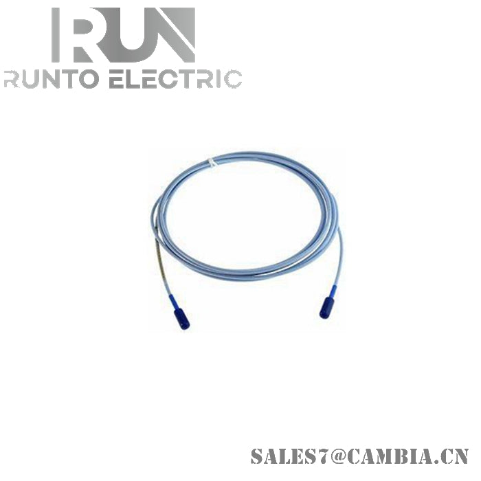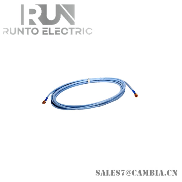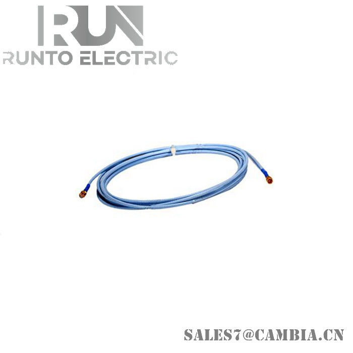
Bently Nevada 330130-040-01-05 3300 XL Standard Extension Cable

Bently Nevada 330130-040-01-05 3300 XL Standard Extension Cable
Configured for signal transmission between proximity probes and Proximitor sensors in 3300 XL transducer systems, the Bently Nevada 330130-040-01-05 (330130 Standard Extension Cable) provides direct electrical interconnection while preserving calibrated system impedance and signal integrity. The cable forms part of a matched eddy-current transducer assembly used for shaft vibration, position, and rotational monitoring measurements.
Suffix Breakdown & Model Matrix
-
330130: 3300 XL Standard Extension Cable
-
040: 4.0 m cable length
-
01: Armored cable with connector protector
-
05: Multiple agency approval option including hazardous area certifications
Hardware Specifications
| Parameter | Specification |
|---|---|
| Model | 330130-040-01-05 |
| Brand | Bently Nevada |
| Origin | United States |
| Product Type | Standard Extension Cable |
| Series | 3300 XL 8 mm |
| Cable Length | 4.0 m |
| Cable Construction | Armored Triaxial Cable |
| Connector Protection | Connector Protector Included |
| Characteristic Impedance | 75 Ohm |
| Cable Capacitance | 69.9 pF/m (21.3 pF/ft) Typical |
| System Compatibility | 3300 XL Probe and Proximitor Sensor |
| Supported System Length | 5 m or 9 m Transducer System |
| Insulation Material | FEP |
| Armor Material | Stainless Steel Armor |
| Connector Design | CableLoc Gold-Plated Connector |
| Pull Strength | 330 N (75 lbf) Maximum |
| Operating Temp | -51 deg C to +177 deg C |
| Compliance | CSA, ATEX, IECEx Approval Option |
| Weight | Approximately 0.25 kg to 0.29 kg |
| Dimensions | 4.0 m Overall Length |
| Power Consumption | Passive Cable Assembly |
Gap Voltage Stability and Cross-Talk Suppression
The 330130 extension cable is a calibrated component within the 3300 XL transducer system. Electrical length, cable impedance, and connector characteristics are controlled to maintain system accuracy and repeatability.
Proper matching between the proximity probe, extension cable, and Proximitor sensor is required to achieve the intended system linearity and gap voltage characteristics. During commissioning, gap voltage verification is commonly performed to confirm that the transducer system operates within its calibrated measurement region, typically centered near the standard -10 VDC operating target.
The triaxial cable construction and continuous shielding arrangement assist in suppressing electromagnetic interference and reducing cross-talk between adjacent monitoring channels installed on the same machine train.
Frequently Asked Questions
Q: Can the extension cable be shortened or field-spliced?
A: No. The cable is part of a calibrated transducer system. Modifying the cable length or connector assembly can alter system characteristics and affect measurement accuracy.
Q: Does the cable require a specific total system length?
A: Yes. The extension cable must be matched with the appropriate 3300 XL probe and Proximitor sensor configuration to achieve the specified 5 m or 9 m system length.
Q: What is the function of the connector protector?
A: The connector protector helps reduce contamination from moisture, lubricants, and industrial contaminants while providing additional mechanical protection at the connection interface.
Field Installation Guidelines
-
Verify probe, extension cable, and Proximitor sensor compatibility before installation.
-
Do not alter cable length or replace factory-installed connectors.
-
Route signal cables separately from motor feeders, VFD output cables, and high-current conductors.
-
Maintain shield continuity throughout the complete transducer system.
-
Prevent excessive bending, crushing, twisting, or tensile loading of the cable assembly.
-
Ensure CableLoc connectors are fully engaged and mechanically secured.
-
Inspect armor, connectors, and protective fittings for physical damage before commissioning.
-
Confirm acceptable gap voltage values after installation and prior to machine startup.
Bently Nevada 330130-040-01-05 3300 XL Standard Extension Cable