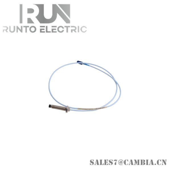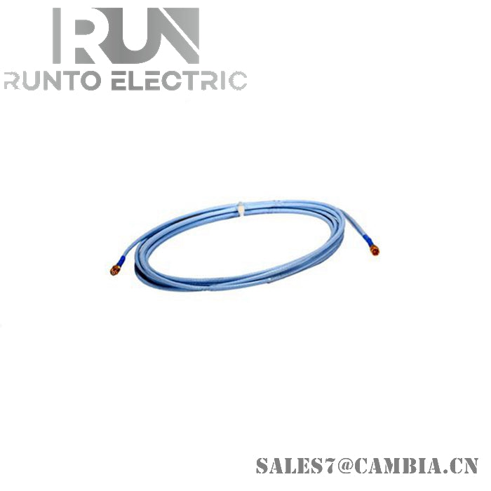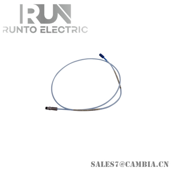
Bently Nevada 330171-00-94-10-02-00 5mm Proximity Probe

Bently Nevada 330171-00-94-10-02-00 3300 5 mm Proximity Probe
The Bently Nevada 330171-00-94-10-02-00 serves as the primary 330171 3300 5 mm Proximity Probe utilized to execute non-contact shaft vibration and position measurement across Bently Nevada 3300 and 3300 XL monitoring platforms. The probe generates an RF-based eddy-current field that responds to conductive target movement and operates as part of a matched transducer system consisting of a probe, extension cable, and Proximitor sensor.
Suffix Breakdown & Model Matrix
-
Armor Option: 00 = Without armor
-
Overall Case Length Option: 94 = 9.4 in case length configuration
-
Total Cable Length Option: 10 = 1.0 m (3.3 ft)
-
Connector Option: 02 = Miniature coaxial ClickLoc connector with standard cable
-
Agency Approval Option: 00 = Not required
Hardware Specifications
| Parameter | Specification |
|---|---|
| Model | 330171-00-94-10-02-00 |
| Brand | Bently Nevada |
| Product Type | 3300 5 mm Proximity Probe |
| Series | 3300 / 3300 XL |
| Origin | U.S.A. |
| Probe Tip Diameter | 5 mm |
| Thread Size | 1/4-28 UNF |
| Armor Option | Without armor |
| Overall Case Length | 9.4 in configuration |
| Total Cable Length | 1.0 m (3.3 ft) |
| Connector Type | Miniature coaxial ClickLoc connector |
| Measurement Principle | Eddy-current proximity sensing |
| Measured Variables | Shaft vibration, shaft position, gap |
| Power Consumption | Determined by associated Proximitor sensor |
| Output System Compatibility | 3300 and 3300 XL transducer systems |
Gap Voltage Validation and Cross-Talk Suppression
The 3300 5 mm probe is intended for installations where available mounting space does not accommodate larger probe diameters. The 5 mm sensing tip enables placement near shafts, collars, and other conductive machine elements in restricted mechanical environments.
As part of a calibrated proximity transducer system, the probe is commonly verified through gap voltage measurements during commissioning. Proper target spacing is required to achieve the expected operating region and measurement linearity. A gap voltage near the specified system target value is typically used to validate probe positioning before vibration data is accepted for machinery analysis.
The miniature coaxial cable construction assists in maintaining signal integrity between the probe and associated Proximitor sensor. Proper cable routing practices help minimize signal cross-talk and electromagnetic interference when multiple transducer channels are installed within the same machinery train.
Frequently Asked Questions
Q: Can this probe directly generate a voltage output for a monitoring rack?
A: No. The probe must operate with a compatible extension cable and Proximitor sensor, which convert the RF signal into a proportional voltage output.
Q: What is the primary advantage of the 5 mm probe tip?
A: The smaller probe diameter allows installation in locations where mechanical clearances limit the use of larger proximity probes.
Q: Does the probe contact the shaft during operation?
A: No. The probe uses a non-contact eddy-current measurement principle and maintains a physical gap from the monitored surface.
Field Installation Guidelines
-
Verify probe, extension cable, and Proximitor part number compatibility before installation.
-
Confirm that the mounting thread matches the machine bracket specification of 1/4-28 UNF.
-
Route transducer cables separately from motor power cables, relay wiring, and variable-frequency drive conductors.
-
Avoid excessive cable bending, crushing, or twisting during installation.
-
Ensure cable shields are terminated according to plant instrumentation grounding practices.
-
Check connector engagement and locking before applying system power.
-
Perform gap voltage validation and channel functional testing after installation and before machinery startup.
Bently Nevada 330171-00-94-10-02-00 5mm Proximity Probe