Bently Nevada 330703-000-050-10-01-00 3300 XL 11 mm Proximity Transducer System

Bently Nevada 330703-000-050-10-01-00 3300 XL 11 mm Proximity Transducer System
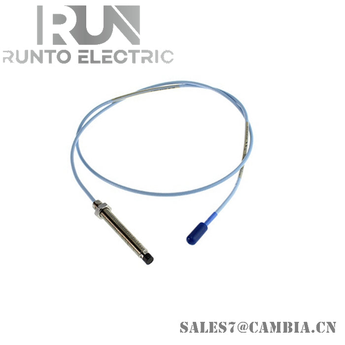
The Bently Nevada 330703-000-050-10-01-00, also cataloged as the 330703 Proximity Probe, operates as a dedicated hardware component for contactless position and vibration measurement within 3300 XL 11 mm transducer systems.
Suffix Breakdown & Model Matrix
- 330703: 3300 XL 11 mm Proximity Probe (M14 x 1.5 thread)
- -000: Unthreaded Length Option (0 mm)
- -050: Overall Case Length Option (50 mm)
- -10: Total Length Option (1.0 meter / 3.3 feet)
- -01: Connector Option (Miniature coaxial ClickLoc connector, standard cable, without armor)
- -00: Agency Approval Option (Not required / Standard, no hazardous area certification)
Hardware Specifications
| Parameter | Specification |
|---|---|
| Model | 330703-000-050-10-01-00 |
| Brand | Bently Nevada |
| Origin | United States |
| Weight | 0.25 kg |
| Dimensions | M14 x 1.5 threads, 50 mm case length, 1.0 m total cable length |
| Operating Temp | -51 to +177 deg C |
| Power Consumption | Passive probe head, driven by Proximitor Sensor (-18 VDC to -24 VDC) |
| Scale Factor / Output | 3.94 V/mm (100 mV/mil) |
| DC Resistance | 5.9 ohms +/- 0.5 ohms |
| Connector Type | Miniature coaxial ClickLoc connector |
| Armor Option | Without armor |
Rotor Dynamics and Eddy-Current Probe Scaling
Eddy-current probe scaling for the 11 mm transducer system yields a linear output sensitivity of 3.94 V/mm (100 mV/mil), providing extended dynamic measurement range compared to standard 8 mm probes. During installation, gap voltage validation target (-10 VDC targets at center gap) ensures the probe operates at the linear midpoint of its calibrated range. Managing cross-talk suppression requires proper radial spacing between adjacent 11 mm probe heads to eliminate magnetic field interference on heavy industrial rotor shafts.
Frequently Asked Questions
Q: Why does the 11 mm probe use a 3.94 V/mm (100 mV/mil) scale factor instead of the standard 7.87 V/mm (200 mV/mil)?
A: The larger 11 mm tip increases the linear measurement range to approximately 4.0 mm (160 mils), which requires adjusting the output slope to 3.94 V/mm to fit within standard -18 VDC to -24 VDC Proximitor power rails.
Q: What is the significance of measuring a DC resistance of 5.9 ohms across the probe connector?
A: A reading of 5.9 ohms +/- 0.5 ohms confirms internal coil and cable continuity, verifying that the winding and coaxial lead are free from open or short circuits prior to connection.
Field Installation Guidelines
- Inspect M14 x 1.5 mounting threads on the machine casing or mounting bracket to verify they are clean and free of metal burrs before inserting the probe.
- Monitor DC output voltage at the associated 3300 XL Proximitor Sensor using a calibrated multimeter, adjusting mechanical thread engagement until achieving a -10 VDC gap setting.
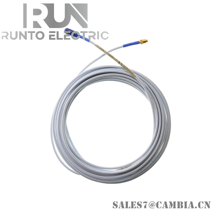
- Route the unarmored 1.0-meter coaxial lead wire through dedicated metal conduit or cable trays to prevent mechanical pinch hazards and electrical noise interference.
- Ensure a minimum coaxial cable bend radius of 25.4 mm (1.0 inch) along the cable path to avoid internal conductor fatigue or impedance alteration.
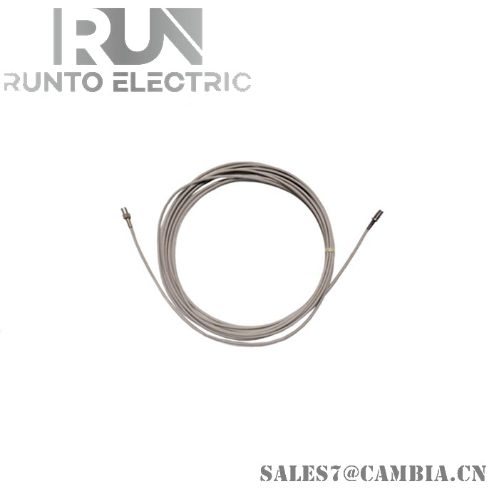
- Join the miniature coaxial ClickLoc connector to the extension cable until the locking mechanism fully engages, wrapping the junction with self-fusing silicone tape to prevent chassis grounding.
Bently Nevada 330703-000-050-10-01-00 3300 XL 11 mm Proximity Transducer System