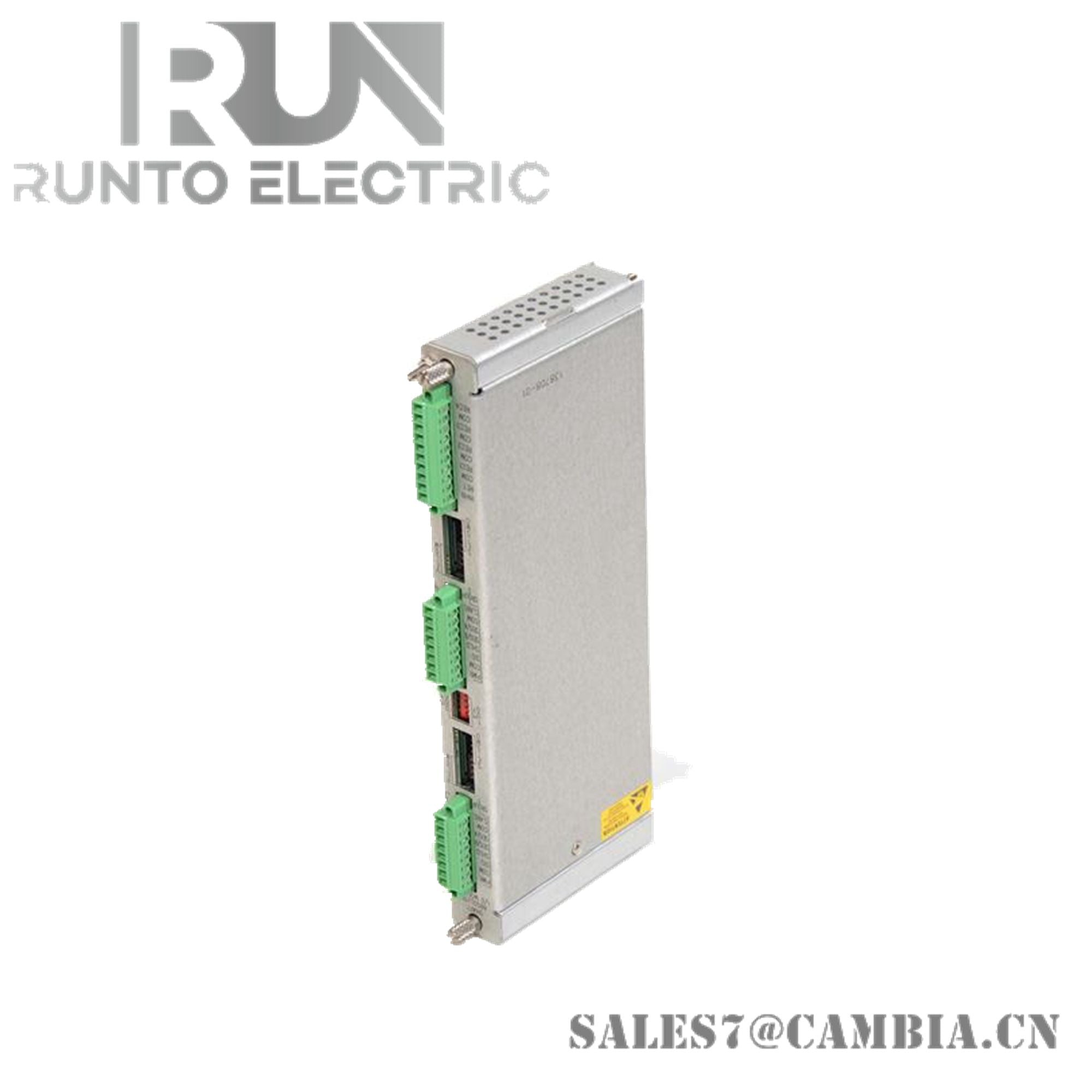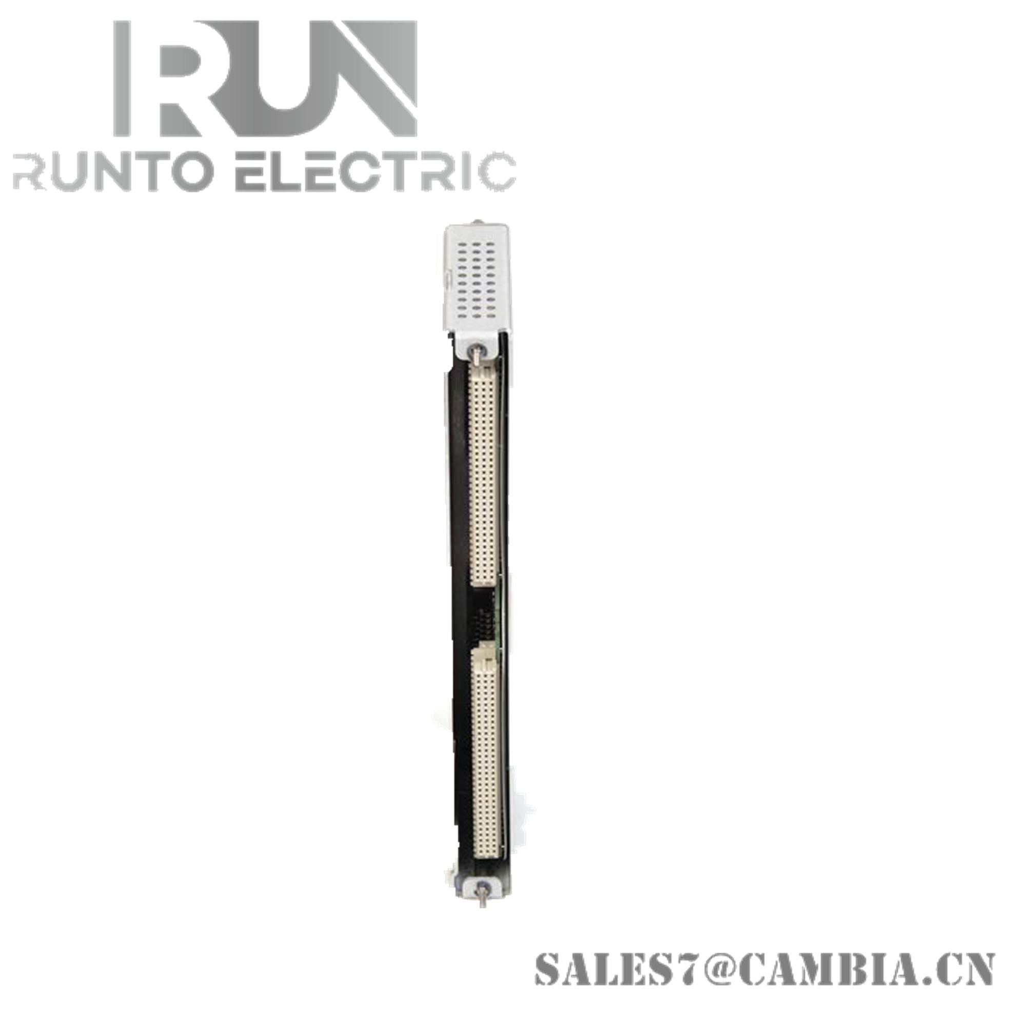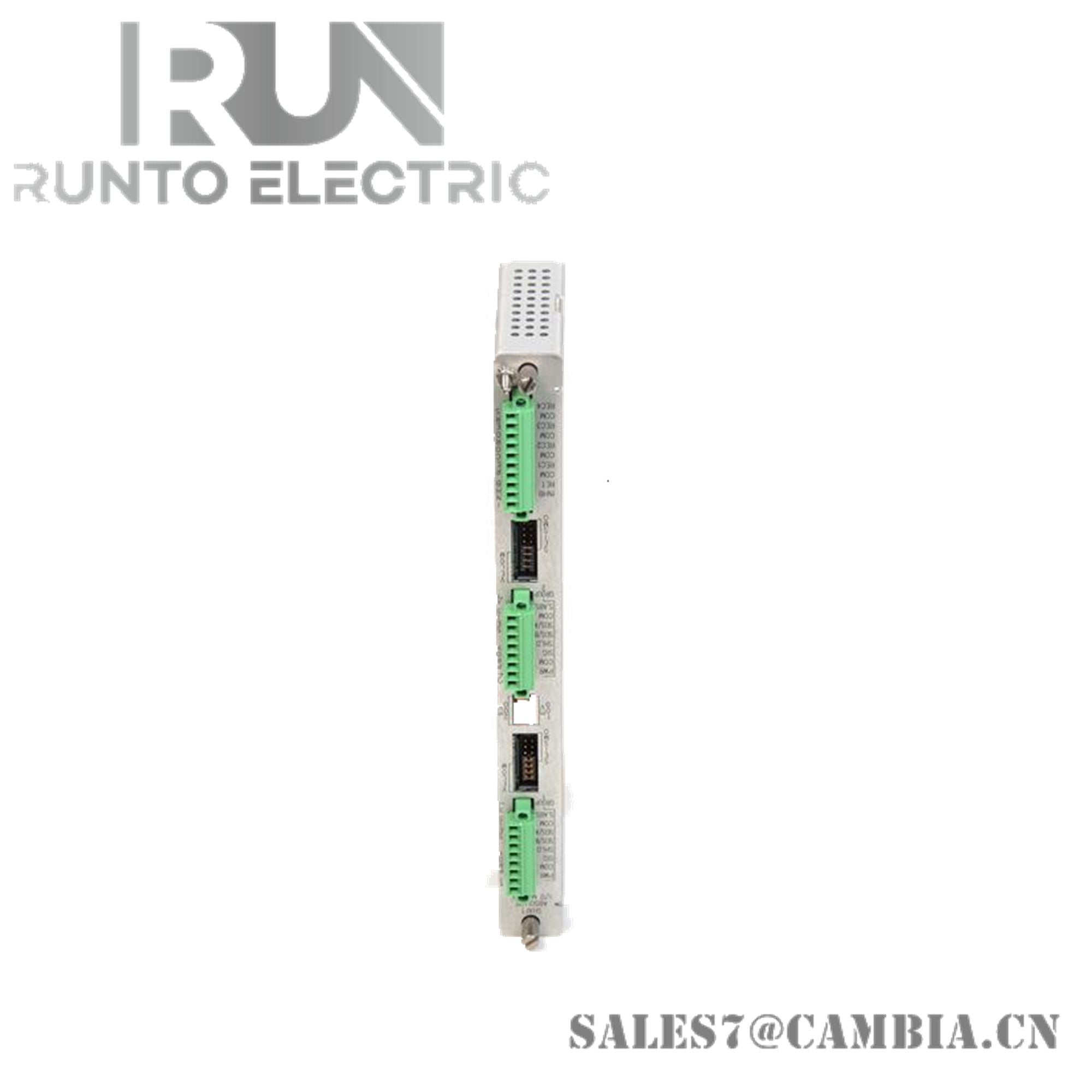
Bently Nevada 3500/42M 138708-01 Shaft Absolute I/O Module

Bently Nevada 3500/42M 138708-01 Shaft Absolute I/O Module
The Bently Nevada 3500/42M 138708-01, also cataloged as the 3500/42M I/O module, operates as a dedicated hardware component for shaft absolute vibration signal acquisition within the 3500 machinery protection system.
Hardware Specifications
| Parameter | Specification |
|---|---|
| Model | 3500/42M 138708-01 |
| Brand | Bently Nevada |
| Origin | U.S.A |
| Weight | 0.20 kg (0.44 lb) |
| Dimensions | 241.3 mm × 24.4 mm × 99.1 mm (9.50 in × 0.96 in × 3.90 in) |
| Operating Temp | -30 deg C to +65 deg C (-22 F to +150 F) |
| Storage Temp | -40 deg C to +85 deg C (-40 F to +185 F) |
| Relative Humidity | 95%, non-condensing |
| Power Consumption | 7.7 W typical |
| Module Type | Shaft Absolute I/O Module |
| Channel Capacity | 4 independent input channels |
| Input Compatibility | Proximity, velocity, acceleration transducers |
| Input Impedance | 10 kΩ (Proximitor and acceleration inputs) |
| Accuracy | ±0.33% typical, ±1% maximum |
| Transducer Supply | -24 VDC |
| Output Supplies | Prox & Velomitor: 23.9 V / 45.5 mA / 1.09 W; Prox & Seismoprobe: 6.82 V / 45.5 mA / 0.31 W |
| Output Impedance | 550 Ω (General), 300 Ω (Shaft Absolute) |
| Voltage Compliance | 0 to +12 VDC across load (0–600 Ω) |
Rotor Dynamics and Cross-Talk Suppression
The 3500/42M integrates with proximitor and seismic transducer systems where eddy-current probe scaling is critical for rotor dynamics analysis. Gap voltage validation at -10 VDC ensures accurate shaft motion interpretation. Cross-talk suppression across the four channels maintains fidelity of vibration signatures, preventing interference between proximity and seismic inputs.
Frequently Asked Questions (FAQ)
Q: Can the 3500/42M module be hot-swapped in a 3500 rack? A: No. Modules must be inserted or removed only when the rack is de-energized to avoid undefined states.
Q: What is the maximum load resistance supported by the output stage? A: The voltage compliance supports 0 to 600 Ω load resistance across the output range.
Q: How is accuracy maintained across different transducer types? A: The module provides ±0.33% typical accuracy by conditioning each input type with dedicated impedance and supply scaling.
Field Installation Guidelines
- Install the module in designated rack slots with full connector engagement.
- Route transducer wiring with shield continuity to minimize EMI.
- Ground shields at the rack end only to prevent ground loops.
- Separate vibration signal cabling from high-current conductors.
- Verify gap voltage and impedance during commissioning to confirm proper transducer biasing.
- Maintain ambient conditions within specified operating temperature and humidity limits.
Bently Nevada 3500/42M 138708-01 Shaft Absolute I/O Module