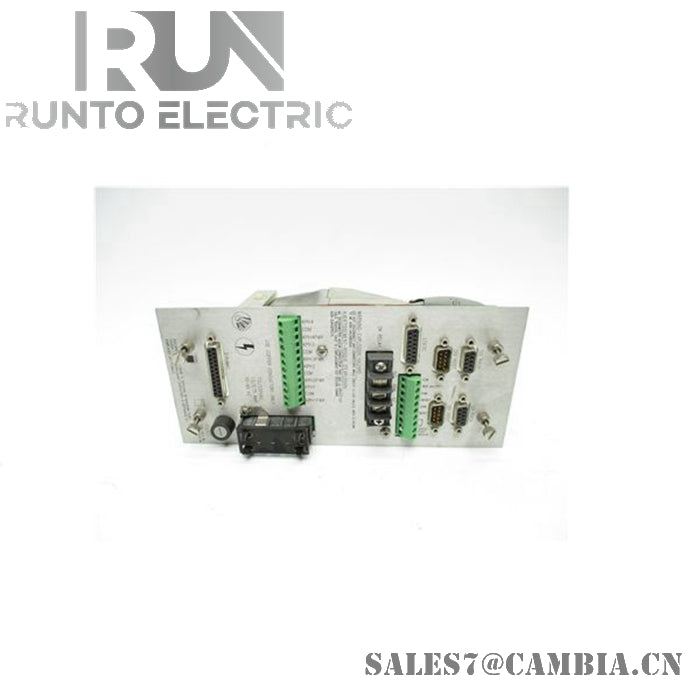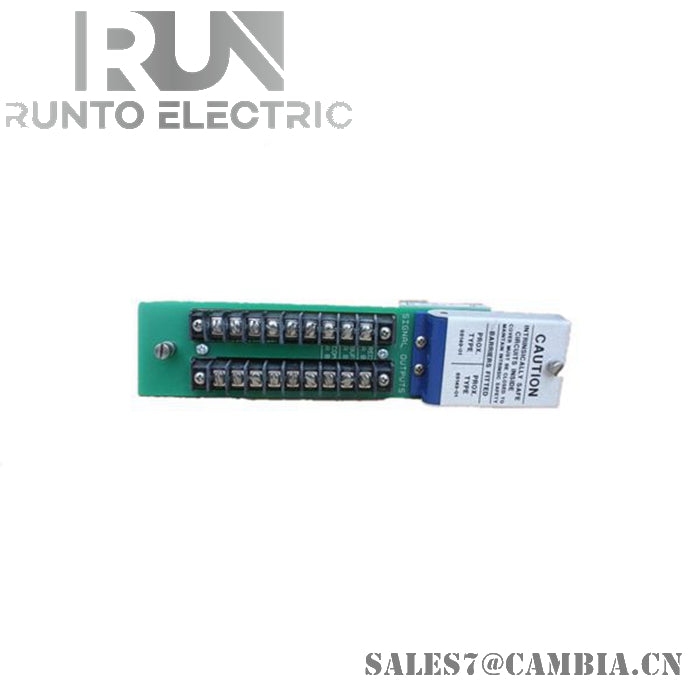
Bently Nevada 88194-01 Power Supply Monitor Unit

Bently Nevada 88194-01 Power Supply Monitor Unit
The Bently Nevada 88194-01, also cataloged as the 88194 Power Supply Monitor Unit, operates as a dedicated hardware component for supplying regulated DC operating power and system status monitoring within the Bently Nevada 3300 Series Monitoring System. The unit accepts configurable AC input ranges, provides programmable transducer supply voltages, incorporates an integral OK relay circuit, and supports continuous operation in machinery protection racks.
Hardware Specifications
| Parameter | Specification |
|---|---|
| Model | 88194-01 |
| Brand | Bently Nevada |
| Origin | Not specified in supplied documentation |
| Product Type | Power Supply Monitor Unit |
| System Compatibility | Bently Nevada 3300 Series Monitoring System |
| Input Voltage (Low Range) | 95 to 125 Vac, single-phase |
| Input Voltage (High Range) | 190 to 250 Vac, single-phase |
| Input Frequency | 50 to 60 Hz |
| Maximum Current Draw | 1.0 A (low range), 0.5 A (high range) |
| Startup Surge Current | 26 A peak or 12 A rms for 1 cycle |
| Configuration Method | Soldered jumper and fuse selection |
| DC Output Options | -24 VDC or -18 VDC user-programmable |
| Output Tolerance | -24 VDC (+0%, -2.5%), -18 VDC (+1%, -2%) |
| Overload Protection | Individual monitor board channel protection |
| OK Relay Type | SPDT, normally energized |
| Relay Sealing | Hermetically sealed |
| Relay Rating (28 VDC) | 5 A resistive |
| Relay Rating (120 VAC) | 5 A resistive |
| Relay Rating (220 VAC) | 3 A resistive |
| Operating Temp | 0 to 65 deg C |
| Storage Temp | -40 to 85 deg C |
| Relative Humidity | Up to 95%, non-condensing |
| Hazardous Area Approval | CSA/NRTL/C Class I, Division 2, Groups A, B, C, D (T4 at 65 deg C) |
| Dimensions | 16 cm x 16 cm x 12 cm |
| Weight | Approximately 0.8 kg |
| Power Consumption | Dependent on connected rack loading; maximum input current specified above |
Gap Voltage Validation for Proximity Monitoring Systems
In 3300 Series machinery protection installations, the power supply provides the regulated transducer excitation required by monitor modules and associated proximity probe circuits. When configured for eddy-current measurement systems, the supplied DC voltage supports proper probe driver operation and assists monitor channels in maintaining valid gap voltage measurements. Gap verification practices commonly target nominal operating regions near -10 VDC to confirm correct probe-to-target positioning and transducer linearity during commissioning.
Frequently Asked Questions
Q: Can the input voltage range be changed in the field?
A: Yes. The power supply is field configurable through internal jumper selection and appropriate fuse replacement for either the 95 to 125 Vac or 190 to 250 Vac operating range.
Q: What occurs if a monitor circuit experiences an overload condition?
A: The unit incorporates individual overload protection associated with each monitor circuit board, helping isolate fault conditions from other monitored channels.
Q: How is system health indicated by the power supply assembly?
A: The unit includes a normally energized hermetically sealed SPDT OK relay located behind the power supply module. Relay state changes can be used by external alarm or status circuits to detect power supply conditions.
Field Installation Guidelines
-
Verify incoming AC voltage range before jumper configuration and fuse installation.
-
Match fuse ratings to the selected operating voltage range.
-
Confirm protective earth grounding is connected according to site electrical standards.
-
Allow adequate clearance around the module to support heat dissipation within the rack enclosure.
-
Route AC input wiring separately from low-level transducer and monitor signal wiring.
-
Inspect relay wiring polarity and terminal assignments before connecting external alarm circuits.
-
After energization, verify correct DC output selection and monitor rack operating status.
-
Where proximity probe monitoring is installed, validate probe gap voltages and transducer power availability before placing machinery into service.
Bently Nevada 88194-01 Power Supply Monitor Unit