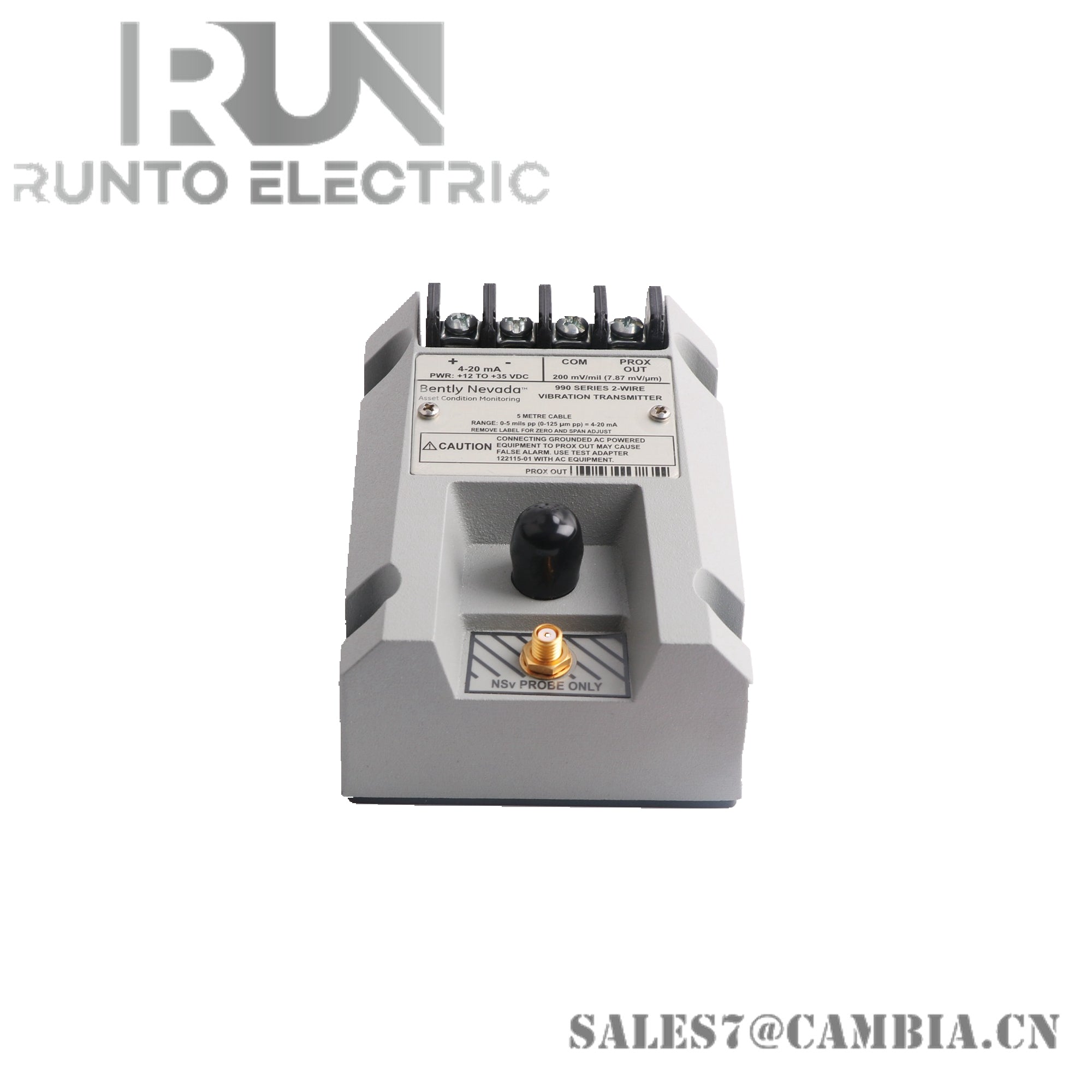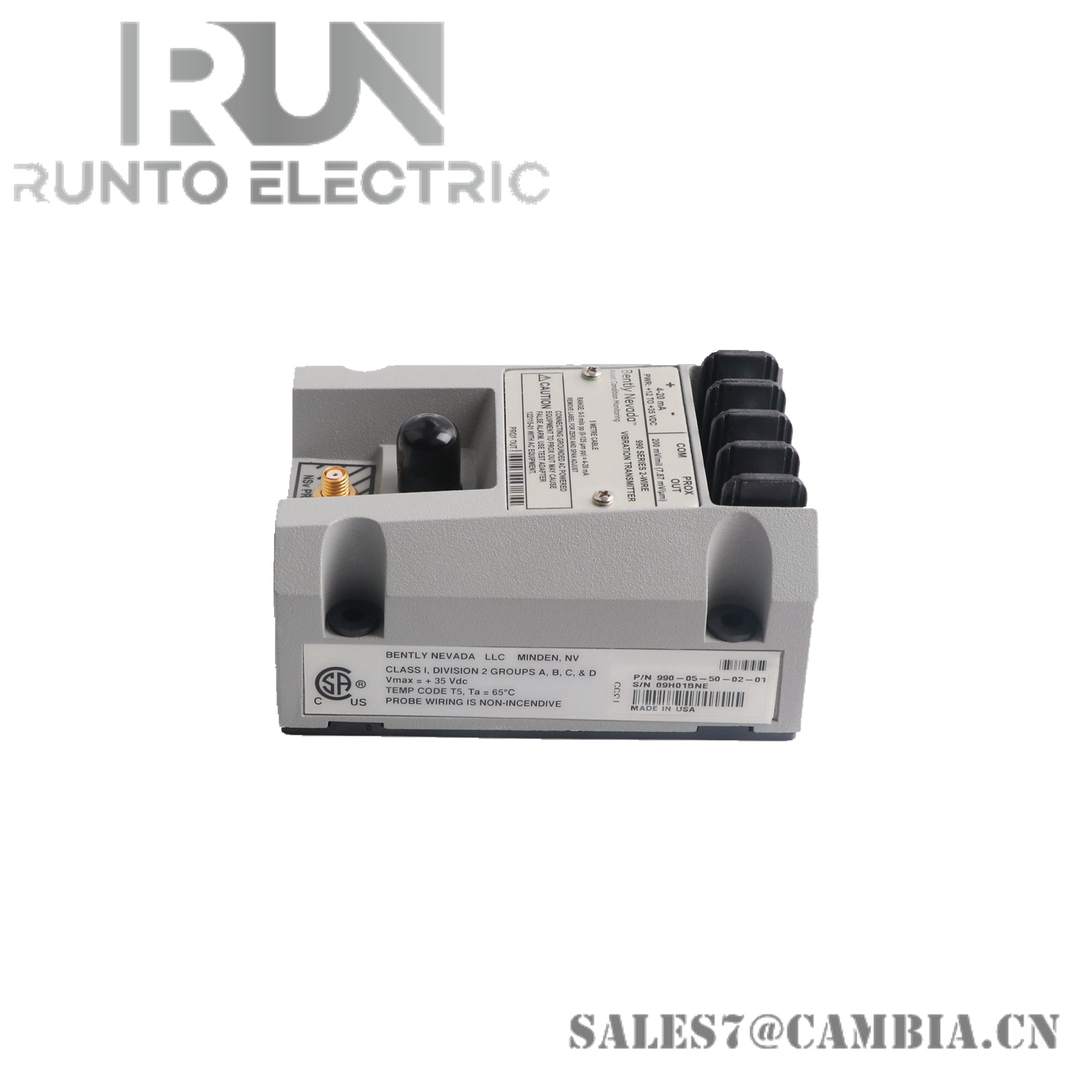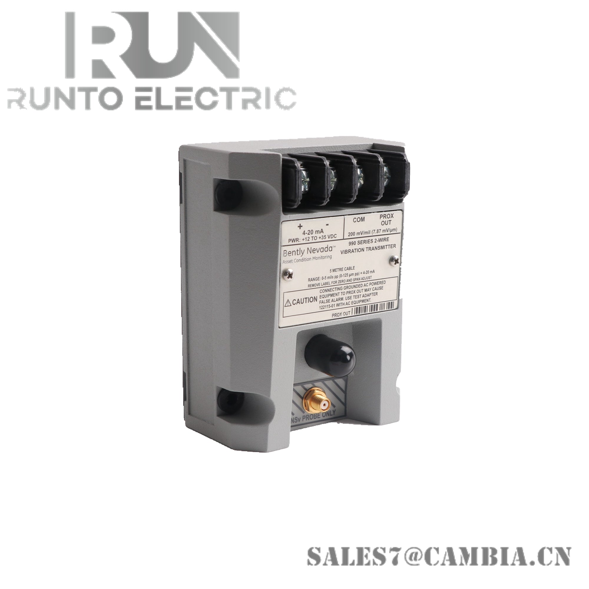
Bently Nevada 990-04-XX-03-00 Vibration Transmitter

Bently Nevada 990-04-XX-03-00 Vibration Transmitter
The Bently Nevada 990-04-XX-03-00, also cataloged as the 990 Vibration Transmitter, operates as a dedicated hardware component for converting shaft vibration measurements into a proportional current-loop signal within machinery protection and condition monitoring systems. The transmitter interfaces directly with Bently Nevada 3300 NSv proximity probe systems and provides a linear 4-20 mA output corresponding to the configured vibration measurement range.
Suffix Breakdown & Model Matrix
The supplied documentation identifies several configuration elements within the 990-04-XX-03-00 ordering structure.
-
990 designates the Vibration Transmitter product family.
-
-04 specifies a measurement range of 0 to 4 mils pp, equivalent to 0 to 100 um pp.
-
-03 identifies the mechanical mounting version supporting 35 mm DIN-rail mounting and direct panel installation.
-
-00 identifies the standard version. No hazardous-area certification is specified in the supplied documentation for this suffix.
-
XX represents an option code not defined in the available source material.
Only suffix information explicitly provided in the supplied documentation is included above.
Hardware Specifications
| Parameter | Specification |
|---|---|
| Model | 990-04-XX-03-00 |
| Brand | Bently Nevada |
| Origin | Not specified in supplied documentation |
| Product Type | Vibration Transmitter |
| Input Signal | Bently Nevada 3300 NSv proximity probe and extension cable |
| Output Signal | 4-20 mA |
| Measurement Range | 0 to 4 mils pp |
| Metric Range Equivalent | 0 to 100 um pp |
| Power Supply | +12 VDC to +35 VDC |
| Maximum Loop Resistance | (Supply Voltage - 12) x 50 Ohm |
| Fault Output | Less than 3.6 mA |
| Frequency Response | 5 Hz to 6 kHz (±3 dB) |
| Buffered Output Interface | BNC connector and terminal output |
| Buffered Output Sensitivity | 7.87 V/mm (200 mV/mil) |
| Mounting Method | 35 mm DIN rail or direct panel mounting |
| Operating Temp | -35 to 85 deg C |
| Storage Temp | -40 to 100 deg C |
| Relative Humidity | 100%, non-condensing |
| Protective Coating | Moisture-protected coated circuitry |
| Hazardous Area Approval | No approval specified for suffix -00 |
Eddy-Current Probe Scaling and Gap Voltage Verification
The 990 transmitter operates in conjunction with Bently Nevada eddy-current proximity sensing technology. Proper commissioning requires verification of probe scaling, extension cable compatibility, and transducer response prior to operation. The associated proximity system should be evaluated using gap voltage measurements to confirm operation within the calibrated linear range. During machinery setup, nominal gap voltage targets near -10 VDC are commonly used to verify probe positioning and appropriate transducer response before accepting vibration measurements for continuous monitoring.
Frequently Asked Questions
Q: What occurs if the proximity probe circuit fails?
A: When a probe cable open circuit, short circuit, or unrecoverable system fault is detected, the transmitter forces the output current below 3.6 mA to indicate a fault condition.
Q: Can diagnostic vibration measurements be taken without interrupting the 4-20 mA loop?
A: Yes. The transmitter includes a buffered voltage output available through both a BNC connection and terminal points for connection of portable vibration analysis instruments.
Q: Is the 4-20 mA output proportional to vibration level?
A: Yes. The output current scales linearly across the configured full-scale vibration range associated with the transmitter model.
Field Installation Guidelines
-
Verify compatibility between the transmitter, 3300 NSv probe, and extension cable before installation.
-
Install the transmitter on a secure 35 mm DIN rail or properly supported panel surface.
-
Keep proximity probe cabling segregated from motor feeders, variable-frequency drive wiring, and other high-energy conductors.
-
Maintain continuous shield integrity from the probe system to the transmitter termination points.
-
Verify loop supply voltage and ensure total loop resistance remains within the permissible calculated limit.
-
Measure and validate gap voltage before commissioning the vibration channel.
-
Use the buffered output for diagnostic measurements rather than disconnecting the process current loop.
-
Inspect cable routing to prevent excessive bending, compression, or mechanical abrasion.
Bently Nevada 990-04-XX-03-00 Vibration Transmitter