Bently Nevada 990-05-70-01-00 Vibration Transmitter

Bently Nevada 990-05-70-01-00 Vibration Transmitter
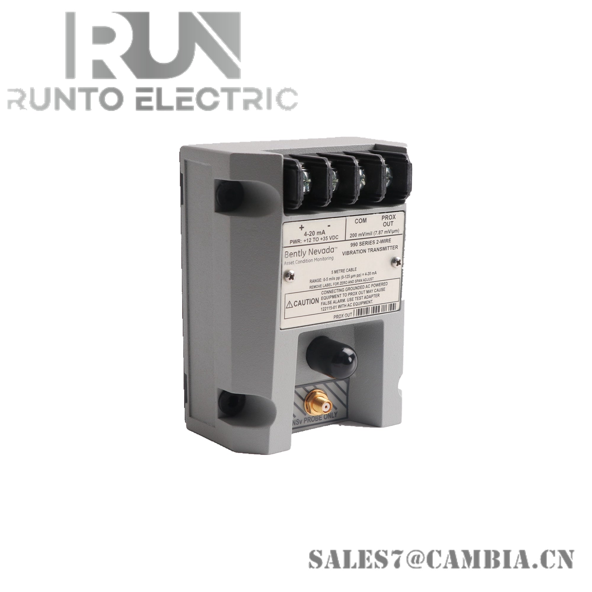
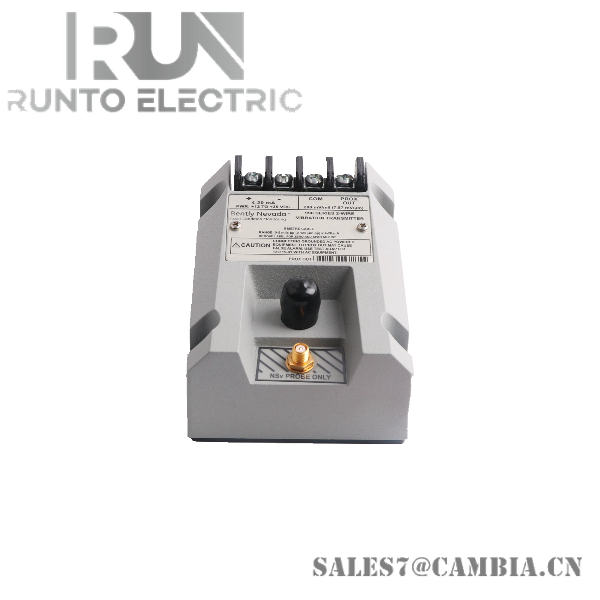
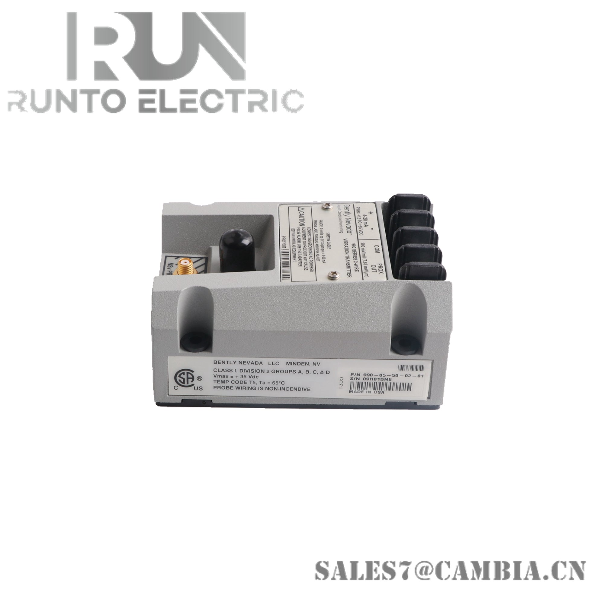
The Bently Nevada 990-05-70-01-00, also cataloged as the 990 Vibration Transmitter, operates as a dedicated hardware component for converting shaft vibration measurements into a proportional 4-20 mA current signal within Bently Nevada machinery monitoring systems. The transmitter interfaces with compatible proximity probe systems and provides continuous vibration monitoring for integration with PLC, DCS, recorder, and protection system inputs.
Suffix Breakdown & Model Matrix
The supplied documentation identifies the following ordering structure for 990-05-70-01-00:
- 990 designates the Vibration Transmitter product family.
- 05 specifies a full-scale measurement range of 0 to 5 mils pp (equivalent to 0 to 125 um pp).
- 70 specifies a 7.0 m transducer system length.
- 01 identifies the 35 mm DIN rail mounting option.
- 00 indicates that no agency approval option is required.
Hardware Specifications
| Parameter | Specification |
|---|---|
| Model | 990-05-70-01-00 |
| Brand | Bently Nevada |
| Origin | United States |
| Product Type | Vibration Transmitter |
| Measurement Range | 0 to 5 mils pp |
| Metric Range Equivalent | 0 to 125 um pp |
| System Length | 7.0 m |
| Mounting Type | 35 mm DIN rail clips |
| Signal Type | Vibration monitoring output |
| Application | Shaft vibration measurement |
| Agency Approval | None specified (Option 00) |
| Country of Manufacture | U.S.A. |
| Weight | Not specified in supplied documentation |
| Shipping Weight | 2 kg |
| Dimensions | Not specified in supplied documentation |
| Operating Temp | Not specified in supplied documentation |
| Power Consumption | Not specified in supplied documentation |
Eddy-Current Probe Scaling and Gap Voltage Validation
The 990 Series transmitter is intended for operation with Bently Nevada eddy-current proximity measurement systems. During commissioning, the associated probe and extension cable assembly should be verified against the specified system length to maintain calibrated sensitivity. Probe gap voltage validation is commonly performed to confirm the transducer operates within its linear measurement zone. For shaft displacement applications, gap voltages approaching the nominal -10 VDC operating region are typically used to verify correct mechanical probe positioning before vibration measurements are accepted for process monitoring.
Frequently Asked Questions
Q: What vibration range does the 990-05-70-01-00 measure?
A: This configuration is specified for a full-scale vibration range of 0 to 5 mils pp, equivalent to 0 to 125 um pp.
Q: What transducer system length is required for this model?
A: The suffix code 70 identifies a 7.0 m probe system length configuration.
Q: How is the transmitter mounted?
A: The suffix code 01 specifies installation using 35 mm DIN rail mounting clips.
Field Installation Guidelines
- Verify that the probe, extension cable, and transmitter all correspond to the specified 7.0 m transducer system length.
- Mount the transmitter securely on a 35 mm DIN rail within a grounded control enclosure.
- Route transducer cables separately from motor feeders, contactor wiring, and variable-frequency drive cabling.
- Maintain continuous cable shielding and grounding practices consistent with site instrumentation standards.
- Validate probe gap voltage prior to commissioning the vibration channel.
- Avoid excessive bending or compression of proximity probe cables.
- Confirm loop wiring polarity before connecting the transmitter output to receiving equipment.
- Verify vibration scaling and alarm settings after startup testing.
Bently Nevada 990-05-70-01-00 Vibration Transmitter