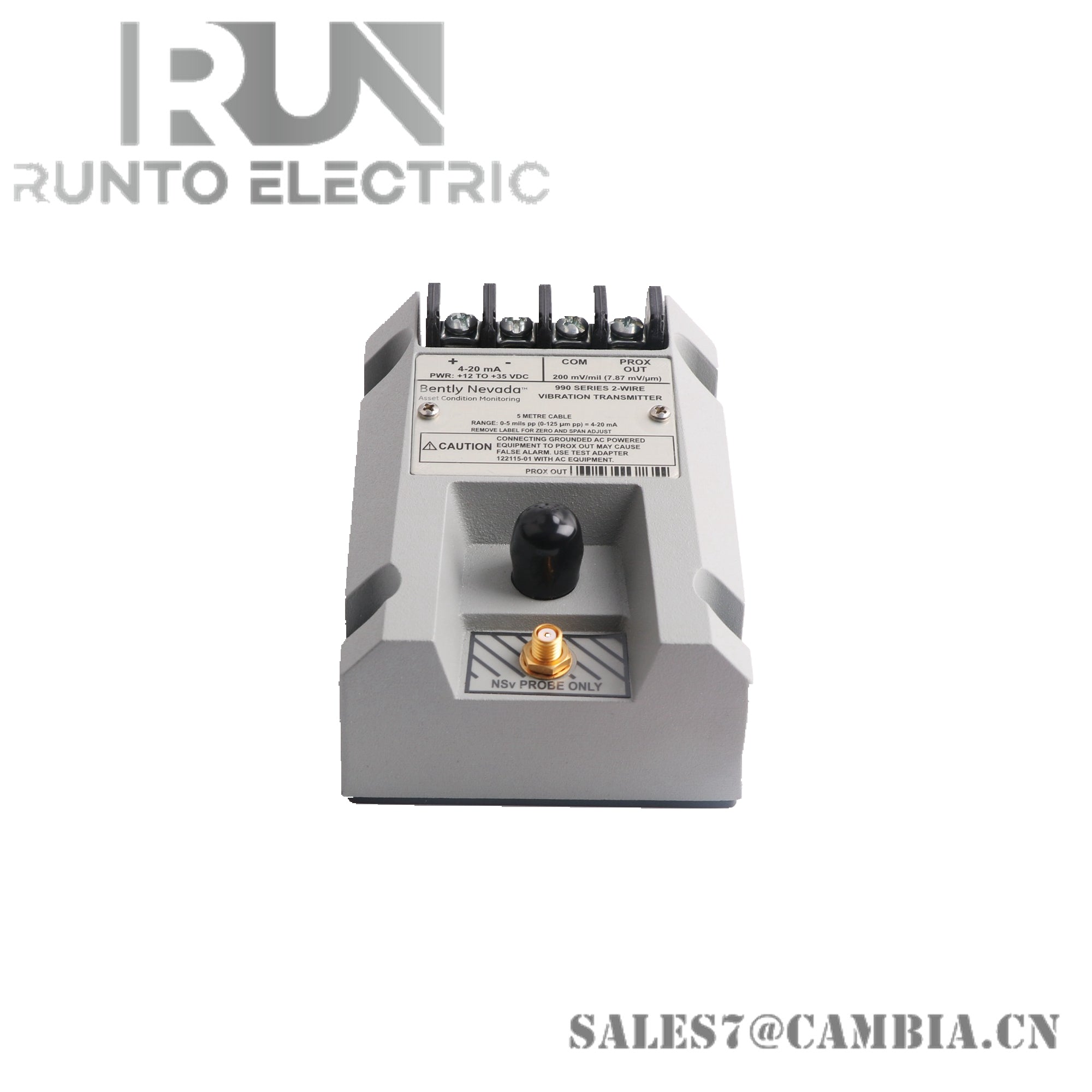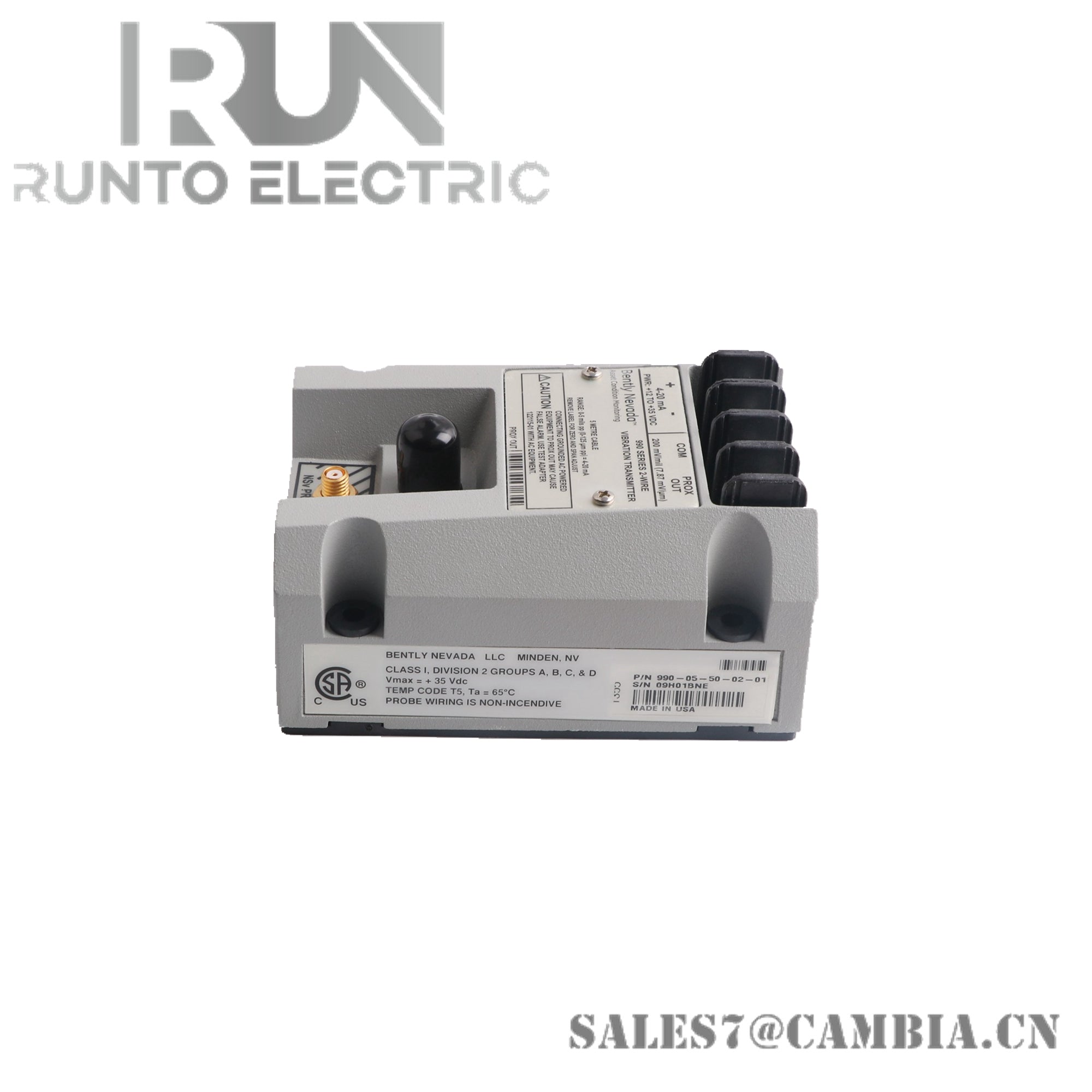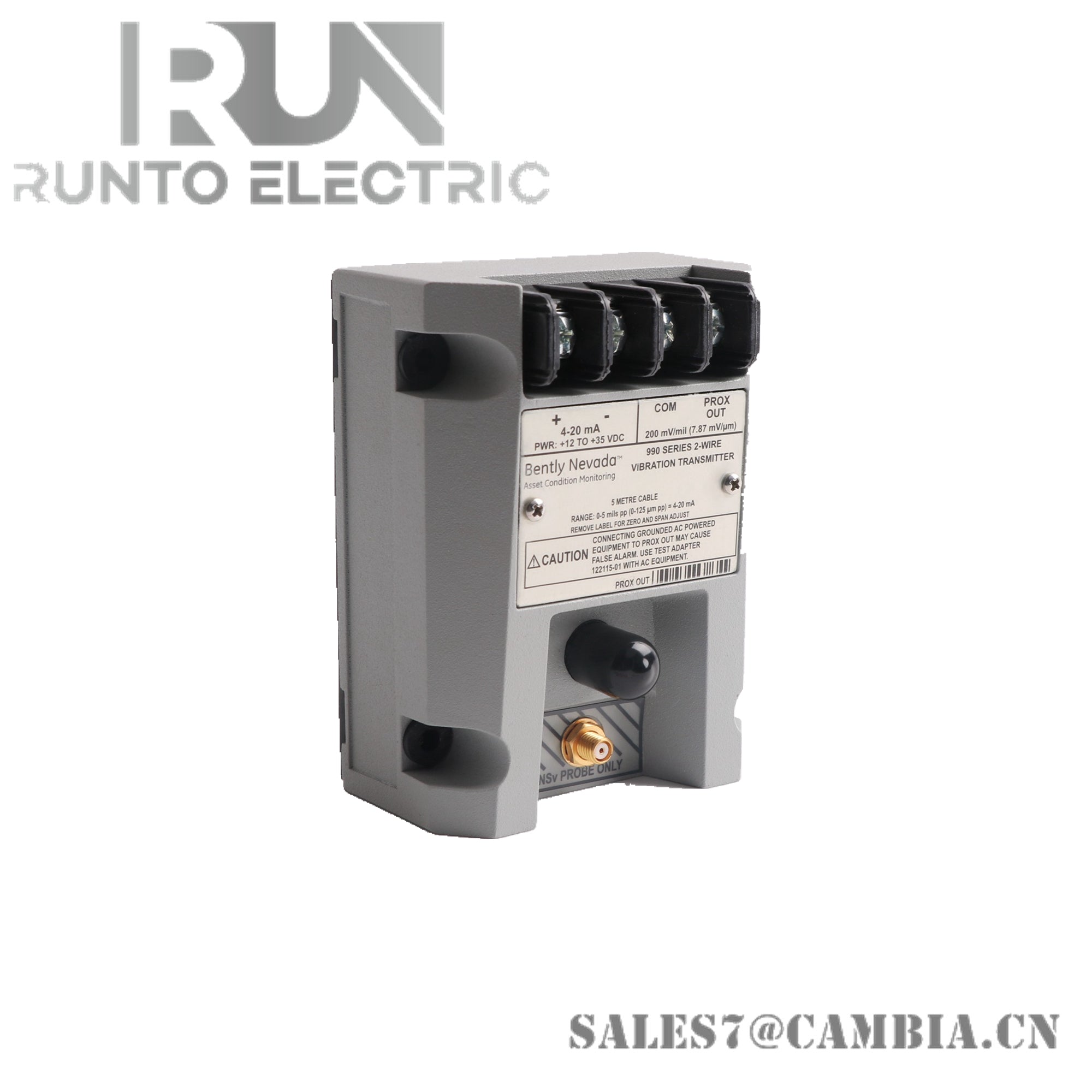
Bently Nevada 991-05-70-01-01 Thrust Transmitter

Bently Nevada 991-05-70-01-01 Thrust Transmitter
Configured for continuous axial shaft position measurement in rotating machinery protection systems, the Bently Nevada 991-05-70-01-01 (991 Thrust Transmitter) provides direct conversion of proximity probe displacement signals into a proportional 4-20 mA output. The transmitter operates with Bently Nevada 3300 NSv proximity probe systems and delivers continuous thrust position monitoring for integration with PLC, DCS, recorder, and protection system inputs.
Suffix Breakdown & Model Matrix
The supplied documentation identifies the following configuration elements within the 991-05-70-01-01 ordering structure.
-
991 designates the Thrust Transmitter product family.
-
05 specifies a current loop measurement range of 0.6-0-0.6 mm (25-0-25 mils).
-
70 identifies a 7.0 m total transducer system length.
-
01 specifies the 35 mm DIN rail mounting option.
-
01 identifies the approved agency-certified version for this configuration.
Only suffix definitions explicitly provided in the supplied documentation are included above.
Hardware Specifications
| Parameter | Specification |
|---|---|
| Model | 991-05-70-01-01 |
| Brand | Bently Nevada |
| Origin | Not specified in supplied documentation |
| Product Type | Thrust Transmitter |
| Output Signal | 4-20 mA DC, 2-wire |
| Supply Voltage | +12 VDC to +35 VDC |
| System Accuracy | ±1.5% of full scale, typical |
| Maximum Loop Resistance | 1000 Ohm at 35 VDC |
| Current Limit | 23 mA typical |
| Fail-Safe Output | Less than 3.6 mA |
| Fail-Safe Response Time | Less than 100 us |
| Recovery Time | Less than 0.1 s |
| Linear Measurement Range | 0.25 mm to 1.65 mm (10 to 65 mils) |
| Full-Scale Range Option | 0.6-0-0.6 mm (25-0-25 mils) |
| Compatible Sensor | Bently Nevada 3300 NSv proximity probe |
| Proximitor Scale Factor | 7.87 mV/um (200 mV/mil) ±6.5% typical |
| Thermal Scale Stability | Within ±10% from 0 to 70 deg C |
| Prox Out Load | 10 MOhm |
| Prox Out Impedance | 10 kOhm |
| System Length | 7.0 m |
| Mounting Method | 35 mm DIN rail |
| Operating Temp | -40 to 85 deg C |
| Humidity | Up to 100% condensing |
| Enclosure Type | Fully potted assembly |
Eddy-Current Probe Scaling and Gap Voltage Validation
The 991 transmitter utilizes eddy-current proximity measurement technology to monitor axial shaft position relative to the machine casing. Proper operation depends on compatibility between the transmitter, 3300 NSv probe, and specified 7.0 m transducer system length. During commissioning, gap voltage verification is commonly performed to confirm operation within the calibrated linear measurement region. For proximity measurement systems, nominal operating targets near -10 VDC are frequently used to validate probe positioning, transducer scaling, and thrust measurement linearity before placing the machine into service.
Frequently Asked Questions
Q: What happens when a Not OK condition occurs?
A: The transmitter forces the output current below 3.6 mA within 100 us after a fault condition is detected. Normal output operation resumes within 0.1 seconds after the condition clears.
Q: Which probe system is supported by the 991-05-70-01-01?
A: The transmitter is designed for operation with a Bently Nevada 3300 NSv proximity probe system.
Q: What is the maximum loop resistance supported by the transmitter?
A: The specified maximum loop resistance is 1000 Ohm, including cable resistance, when operating from a 35 VDC supply.
Field Installation Guidelines
-
Verify compatibility between the transmitter, probe, and extension cable before installation.
-
Confirm that the complete transducer system length matches the specified 7.0 m configuration.
-
Install the transmitter on a secure 35 mm DIN rail inside a grounded enclosure.
-
Route proximity probe wiring separately from motor power cables and high-energy switching circuits.
-
Maintain cable shield continuity according to site instrumentation standards.
-
Validate probe gap voltage prior to commissioning thrust measurement channels.
-
Confirm loop supply voltage remains within the specified 12 VDC to 35 VDC operating range.
-
Verify 4-20 mA scaling at the receiving control or monitoring system before placing equipment into operation.
Bently Nevada 991-05-70-01-01 Thrust Transmitter