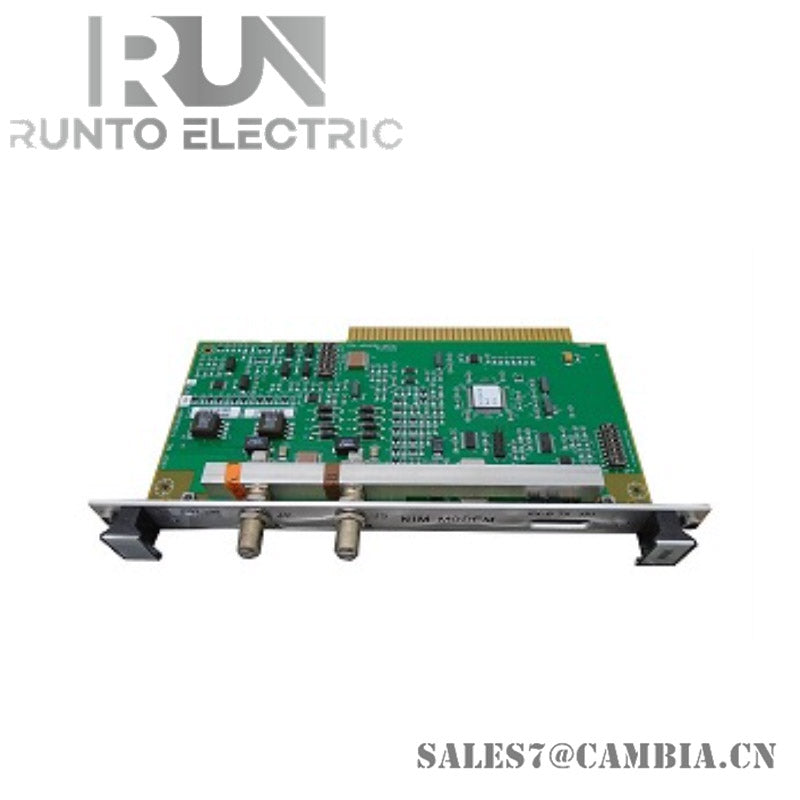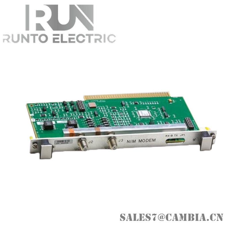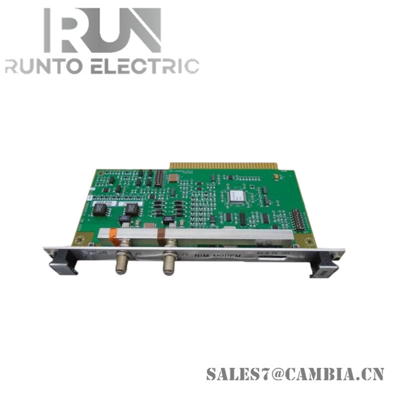
Honeywell 51305508-200 XLCNE2 Paddle Board

Honeywell 51305508-200 XLCNE2 Paddle Board
The Honeywell 51305508‑200, also cataloged as the XLCNE2 paddle board, operates as a dedicated fiber‑optic extender interface for multi‑mode ST‑type LCN links within Honeywell TDC 3000 and selected Experion PKS network segments.
Hardware Specifications
| Parameter | Specification |
|---|---|
| Model | 51305508‑200 |
| Brand | Honeywell |
| Origin | United States |
| Weight | ~0.44 lbs (0.2 kg) |
| Dimensions | 2.0 cm × 13.5 cm × 23.7 cm |
| Operating Temp | Standard industrial ambient range |
| Power Consumption | Passive PC board (no active load) |
| Module Type | LCN extender paddle board |
| Fiber Type | Multi‑mode |
| Connector Type | ST fiber optic connectors |
| Compliance | CE certified |
| System Platform | Honeywell TDC 3000 / Experion PKS |
| Integration Notes | Replaces LCNE / LCNE2 legacy boards |
Channel‑to‑Channel Isolation in Honeywell LCN Fiber Links
Within Honeywell DCS architectures, the paddle board maintains deterministic separation between A‑cable and B‑cable fiber paths. This prevents cross‑talk between redundant LCN channels and stabilizes optical signal levels across multi‑mode ST interfaces. The isolation behavior aligns with Honeywell’s broader process‑control design practices, including predictable boundaries used in 4‑20 mA HART loop protocol and Fieldbus/Profibus gateway modules.
Frequently Asked Questions
Q: How many paddle boards are required for a full fiber extension link? A: A typical deployment uses four boards, one for each A and B cable at both ends of the fiber link.
Q: Does the module include any active optical amplification? A: No. It is a passive PC board designed for connector routing and mechanical integration.
Q: Can the board be mixed with older LCNE or LCNE2 units? A: It is designed as a replacement, but mixed operation depends on the specific LCN segment configuration.
Field Installation Guidelines
- Install paddle boards in matched A/B pairs at both ends of the fiber extension.
- Maintain correct ST connector seating to avoid optical loss.
- Route multi‑mode fiber with controlled bend radius to prevent attenuation.
- Ensure cabinet grounding continuity to minimize EMI coupling into adjacent wiring.
- Verify LCN link integrity using segment diagnostics after installation.
Honeywell 51305508-200 XLCNE2 Paddle Board