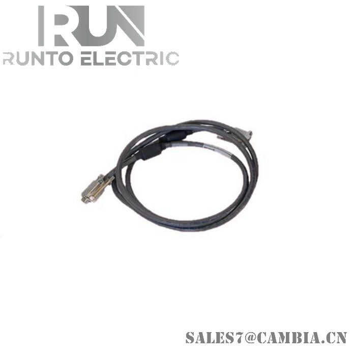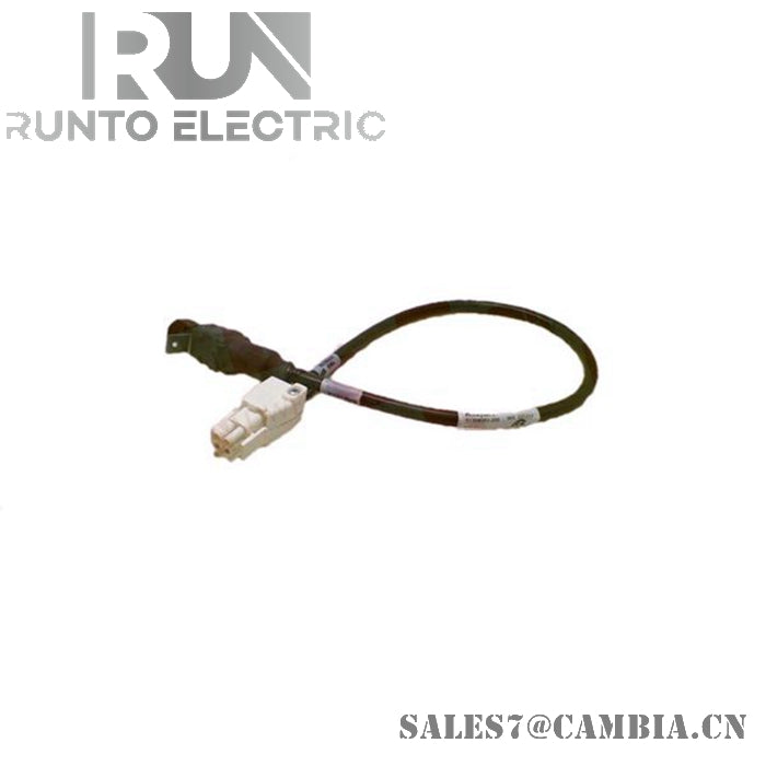
Honeywell 51305943-100 Shielded Communication Cable

Honeywell 51305943-100 Shielded Communication Cable
The Honeywell 51305943-100, also cataloged as the 51305943 cable assembly, operates as a dedicated hardware component for signal transfer within Experion PKS communication paths. Its shielded construction maintains stable low‑level data propagation while preventing EMI/RFI coupling into adjacent DCS wiring.
Hardware Specifications
| Parameter | Specification |
|---|---|
| Model | 51305943-100 |
| Brand | Honeywell |
| Origin | USA |
| Weight | Approx. 300 g to 500 g (packaged) |
| Dimensions | 300 m total length |
| Operating Temp | -40 deg C to +85 deg C |
| Power Consumption | Passive interconnect |
| Conductor Diameter | 22 AWG |
| Cable Type | Industrial shielded communication cable |
| Jacket Material | Heavy‑duty polyurethane |
| Jacket Properties | Abrasion, chemical, and weathering resistance |
| Interference Resistance | EMI/RFI shielding |
| Storage Temperature | -40 deg C to +85 deg C |
Channel‑to‑Channel Isolation in Honeywell DCS Networks
The shielding structure supports stable operation in mixed‑signal environments where 4‑20 mA HART loops or Fieldbus/PA segments coexist with digital communication lines. The polyurethane jacket and internal foil/braid layers suppress cross‑talk, maintaining deterministic behavior for Honeywell I/O assemblies. Cold junction compensation (CJC) circuits in adjacent modules remain unaffected due to the cable’s non‑conductive isolation and controlled thermal profile.
Frequently Asked Questions
Q: Can the cable be used near high‑voltage AC feeders? A: Yes, the EMI/RFI shielding reduces induced noise, but physical separation is recommended to avoid mechanical wear from vibration or heat.
Q: Does the cable support hot‑swap at termination blocks? A: The cable is passive; hot‑swap capability depends on the connected DCS or PLC module. The cable imposes no electrical switching constraints.
Q: Are protocol conversions affected by cable length? A: The 300 m length is suitable for standard shielded communication runs. Latency and attenuation depend on the connected protocol hardware, not the passive cable.
Field Installation Guidelines
- Maintain shield continuity by grounding the drain wire at a single designated point to prevent ground‑loop formation.
- Route the cable away from sharp tray edges to avoid jacket abrasion.
- Avoid tight bend radii to preserve internal shield geometry.
- Segregate communication wiring from high‑energy conductors inside trays.
- Verify connector torque and strain‑relief engagement before energizing associated modules.
Honeywell 51305943-100 Shielded Communication Cable