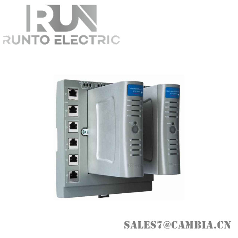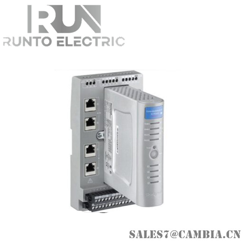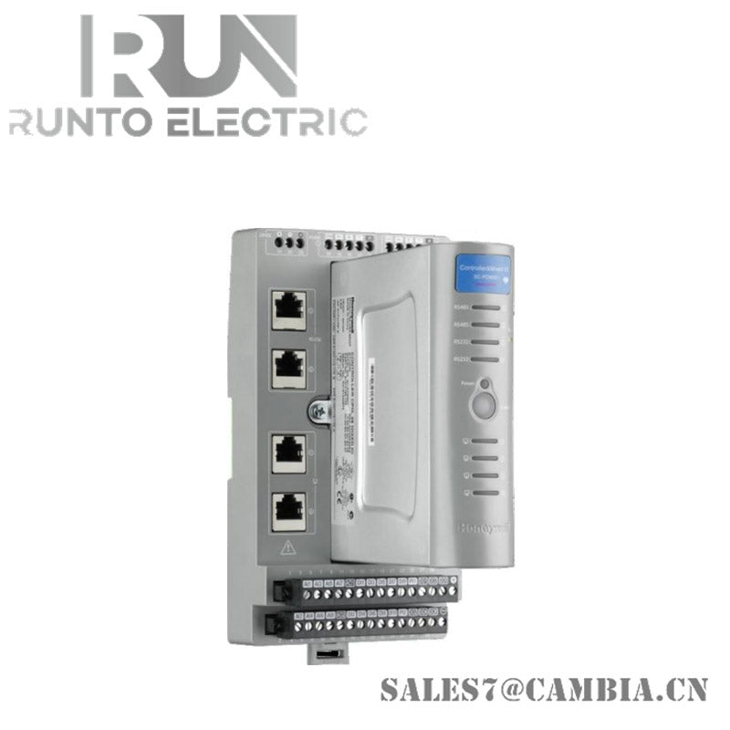
Honeywell SC-UMX01 Mixed I/O Module

Honeywell SC-UMX01 Mixed I/O Module
Configured for mixed signal acquisition in Honeywell control networks, the Honeywell SC-UMX01 (UMX01 Mixed I/O Module) provides direct physical execution of analog and digital input/output functions.
Hardware Specifications
| Parameter | Specification |
|---|---|
| Model | SC-UMX01 |
| Brand | Honeywell |
| Origin | Manufacturer origin not specified |
| Weight | 680 g (approx. 1.5 lbs) |
| Dimensions | 190 mm H × 99 mm W × 141 mm D |
| Operating Temp | -20 to +60 deg C |
| Power Consumption | 2.0 W typical |
| Input Channels | 28 mixed onboard channels |
| Analog Inputs | Configurable 0–10 VDC or 4–20 mA |
| Analog Outputs | 4 channels, 4–20 mA, 12-bit, 750 Ω max load |
| Digital Inputs | 8 channels, 24 VDC, configurable pull-up/pull-down |
| Digital Outputs | 4 channels, 24 VDC, 0.5 A max |
| Isolation | 1500 VDC circuit-to-logic |
| Rated Input Voltage | 24 VDC ±25% |
| Operating Voltage Range | 18–30 VDC |
| Protocols | Modbus RTU, DNP3, Ethernet/IP |
4-20 mA HART Loop Protocol
The SC-UMX01 supports integration with 4-20 mA HART loop protocol, enabling simultaneous analog signal transmission and digital parameter communication. This allows configuration and diagnostics without interrupting process signals. Channel-to-channel isolation ensures that disturbances in one loop do not propagate to adjacent circuits.
Frequently Asked Questions
Q: Does the SC-UMX01 support hot-swap replacement? A: The module is designed for chassis-mounted installation; hot-swap is not supported. Power-down is required before replacement.
Q: What is the backplane current load during operation? A: The module consumes approximately 2.0 W, translating to a low current draw from the 24 VDC backplane supply.
Q: Is firmware upgrade possible without removing the module? A: Firmware updates are executed via the system controller; the module remains installed during upgrade procedures.
Field Installation Guidelines
- Ensure proper shield grounding for analog input wiring to minimize noise.
- Maintain separation between digital output cabling and analog signal lines to reduce interference.
- Observe correct DIN rail mounting and secure mechanical engagement before energizing.
- Verify backplane connector alignment to avoid bent pins or intermittent contact.
- Follow standard industrial practice of 5–95% RH non-condensing environments for installation.
Honeywell SC-UMX01 Mixed I/O Module