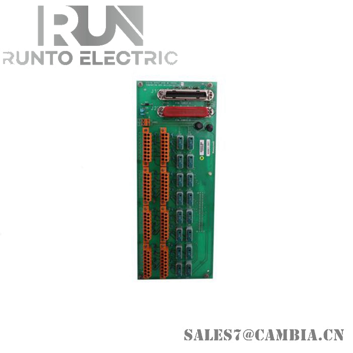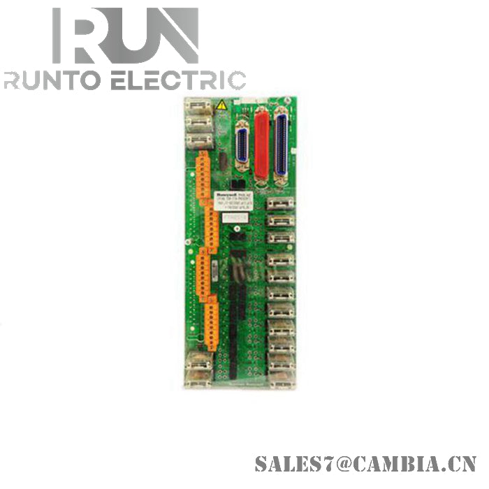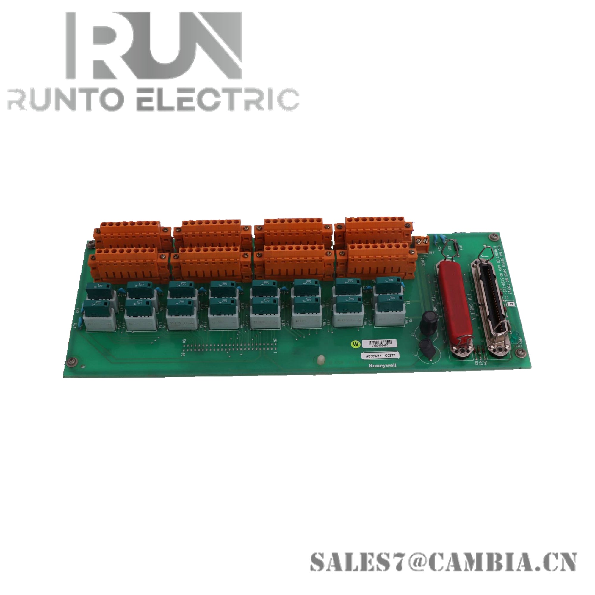
MC-TDIA22 51304431-175 | Honeywell | Digital Input Field Termination Assembly

Honeywell MC-TDIA22 Digital Input Field Termination Assembly
The Honeywell MC-TDIA22, also cataloged as the 51304431-175 digital input field termination assembly, operates as a dedicated hardware component for 24 VDC discrete‑signal termination across Honeywell process‑control platforms.
Hardware Specifications
| Parameter | Specification |
|---|---|
| Model | MC‑TDIA22 |
| Brand | Honeywell |
| Origin | Not specified |
| Weight | 3 kg (shipping) |
| Dimensions | Not specified |
| Operating Temp | Not specified |
| Power Consumption | Passive termination assembly |
| Power Supply | 24 VDC |
| Number of Inputs | 32 digital inputs |
| Product Type | Digital Input Field Termination Assembly |
| System Use | System control and data acquisition devices |
4-20 mA HART Loop Protocol & Channel Isolation
Although the MC‑TDIA22 handles discrete signals rather than analog loops, its integration within Honeywell DCS architectures preserves channel‑to‑channel isolation by maintaining uniform termination geometry and minimizing conductive coupling between adjacent 24 VDC circuits. This isolation behavior prevents noise propagation from mixed wiring bundles and ensures deterministic digital state acquisition for upstream controller modules.
Frequently Asked Questions
Q: Can the MC‑TDIA22 be removed while the controller remains powered? A: Mechanical removal is possible, but all 24 VDC digital channels routed through the assembly will drop out immediately. Hot‑swap is not recommended unless the controller is placed in a safe operating state.
Q: Does the termination assembly draw current from the backplane? A: No. It is a passive device and does not impose electrical load on the controller backplane.
Q: Are there wiring restrictions for high‑density digital inputs? A: Maintain consistent stripping lengths and avoid mixing high‑voltage conductors within the same routing bundle to reduce induced noise on 24 VDC digital lines.
Field Installation Guidelines
Route 24 VDC digital wiring separately from analog or high‑voltage conductors. Maintain proper screw‑terminal torque to ensure stable compression and prevent intermittent digital states. Use shielded cable only when required by the specific digital input module; ground shields at a single point to avoid circulating currents. Verify continuity and correct polarity for each input channel before commissioning.
MC-TDIA22 51304431-175 | Honeywell | Digital Input Field Termination Assembly